WELCOME TO MY STERN WHEEL PADDLE BOAT BUILD
I am presently reconstructing my third paddle wheel boat build. I started this site to chronicle the builds, so I would have a quick way to reference my past projects. I hope you follow along and please write if you have any questions, or (and I do mean it) any suggestions.
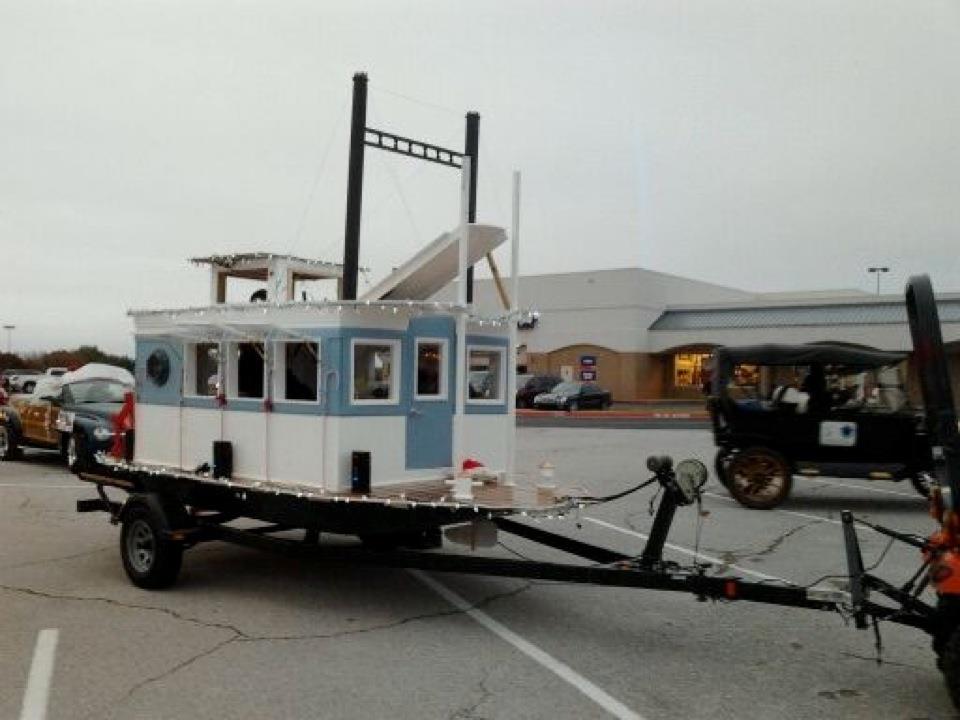
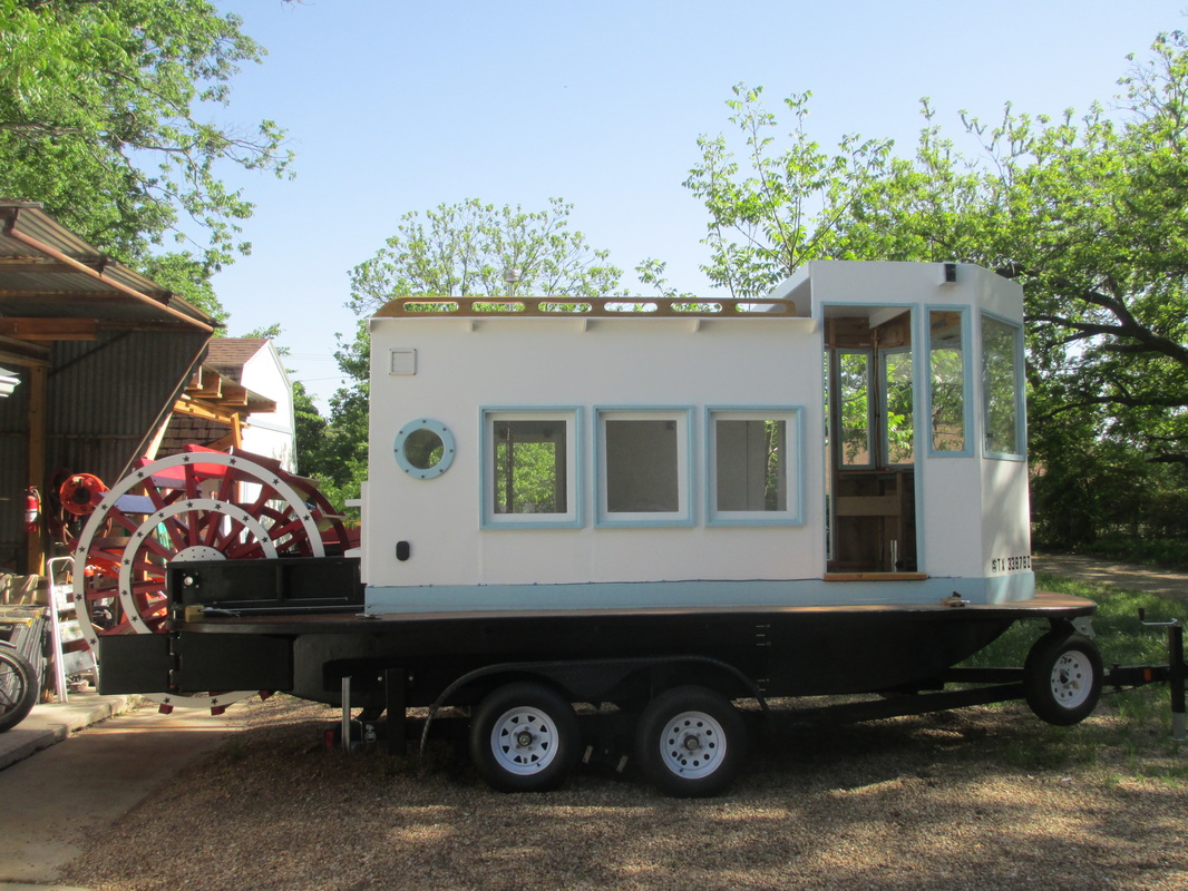
The first boat never survived the winter, so the only time it was afloat was when it was a float in the Christmas parade. This was the project where I learned how to seal plywood properly. The second boat's hull was too shallow, for the deck was only about 2" above the waterline. It never had any speed and the steering was poor. It used to have a second deck where the pilot house used to be, but boy was it top heavy. Third boat floats and steers great. I finally got the correct gear ratio to get the most out of my 40 hp engine, meaning the best ratio between power and speed. The engine was meant for a power washer, so did not have much range of speeds, so I began reconstruction for the hull to hold a larger motor with an auto-transmission from a car.
The first boat never survived the winter, so the only time it was afloat was when it was a float in the Christmas parade. This was the project where I learned how to seal plywood properly. The second boat's hull was too shallow, for the deck was only about 2" above the waterline. It never had any speed and the steering was poor. It used to have a second deck where the pilot house used to be, but boy was it top heavy. Third boat floats and steers great. I finally got the correct gear ratio to get the most out of my 40 hp engine, meaning the best ratio between power and speed. The engine was meant for a power washer, so did not have much range of speeds, so I began reconstruction for the hull to hold a larger motor with an auto-transmission from a car.
Boat build one
|
Boat Build two after removing second deck to remove being top heavy
|
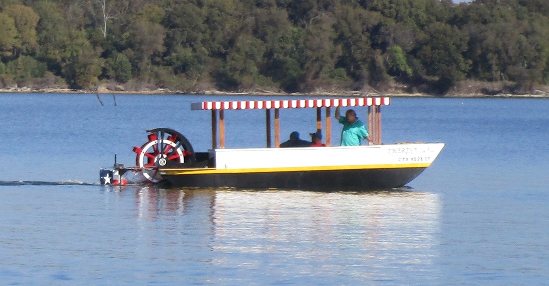
Fun to sail and very safe, but no speed
Links to SUPPLIERS
Bentley's Marine Seat Seats
Go Kart Supply Gear box, driver, torqu converter, and belt
BMI KARTS&SUPPLIES Clutches
MCmaster-Carr Gears, chains, axles, bearings and pulleys
Glen-L Epoxy, resin, silica and microsphere filler, and steering running gear
GO 2 MARINE Lights, blower exhaust hose, gas tank, gas hoses, gas tank filler
OPE Engines Engines
Kohler Engines Remote Throttle and Choke Linkages
HUB CITY Bearings and mounts
RCPW H7 Series Shaft Yokes and needle bearings
Getaprop.com ZF Split Coupling for ZF gearbox
MFG Supply 94C Clutch and 90D Driven (Torque converter)
ANOTHER GOOD SITE FOR INFO: STERNWHEEL RIVERBOAT HARBOR
Newest Progress on Stern Wheel Paddle Boat
Most Recent Progress
5/14/2024 What a year it has been. Total solar eclipse, northern lights over Texas, and I have been to Hobbiton Shire, New Zealand.
11/11/2023 Happy Holidays.
09/7/2023 Just popping in to say am alive and still busy. But truly want to build my next boat.
06/16/2022 I am so sorry that I have not found time to get back to the site. Just been so busy. All is well.
06/16/2022 I am so sorry that I have not found time to get back to the site. Just been so busy. All is well.
08/12/2022 Well, I finally tested positive for covid. Thankfully can't tell any difference between this and a normal sinus infection.
05/07/2022 Hey all, yes I am alive, but have been very busy. I am now in charge of church facilities. I still hope to get back to the boat build this year.
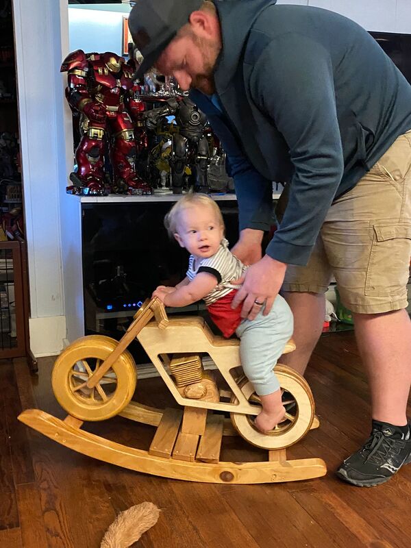
10/19/2021 Hello all! Just letting you all know all is well. Just have been busy with other projects. I follow several blogs that have not been updated for quite a while, and worry if the person had been hit hard by covid. Well that, by the grace of God, has not been the case for us. I was able to complete four cycle-rockers, and have been watching my granddaughter two days every week, 8 hours a day.
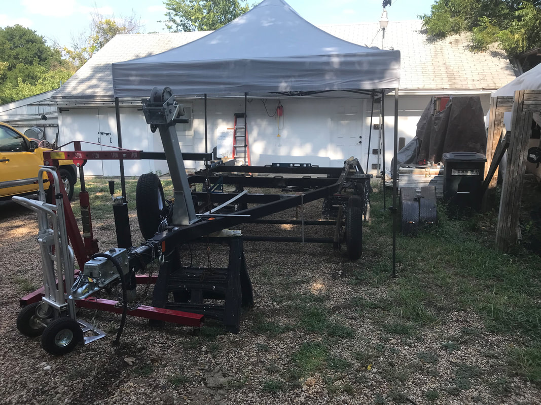
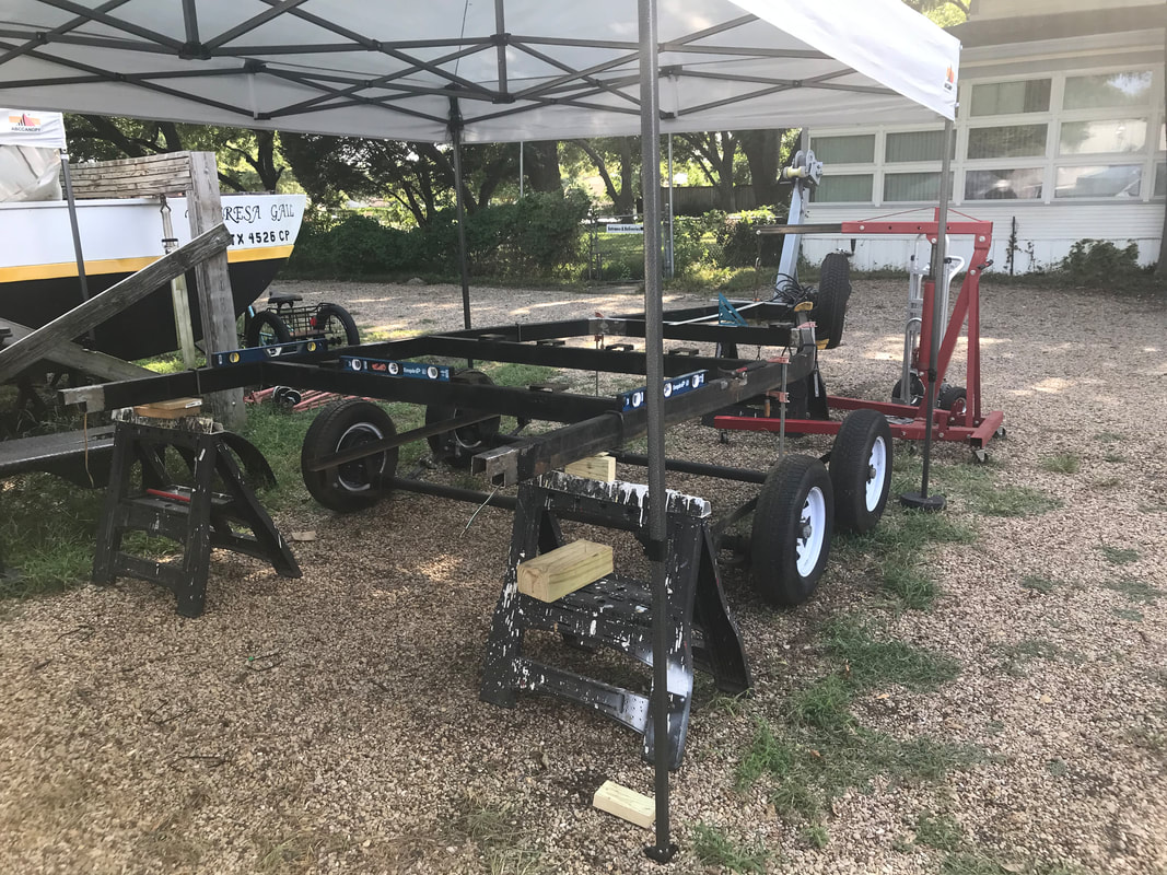
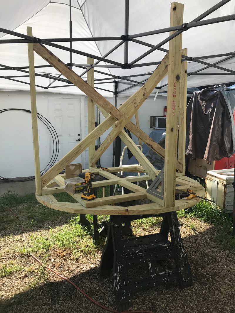
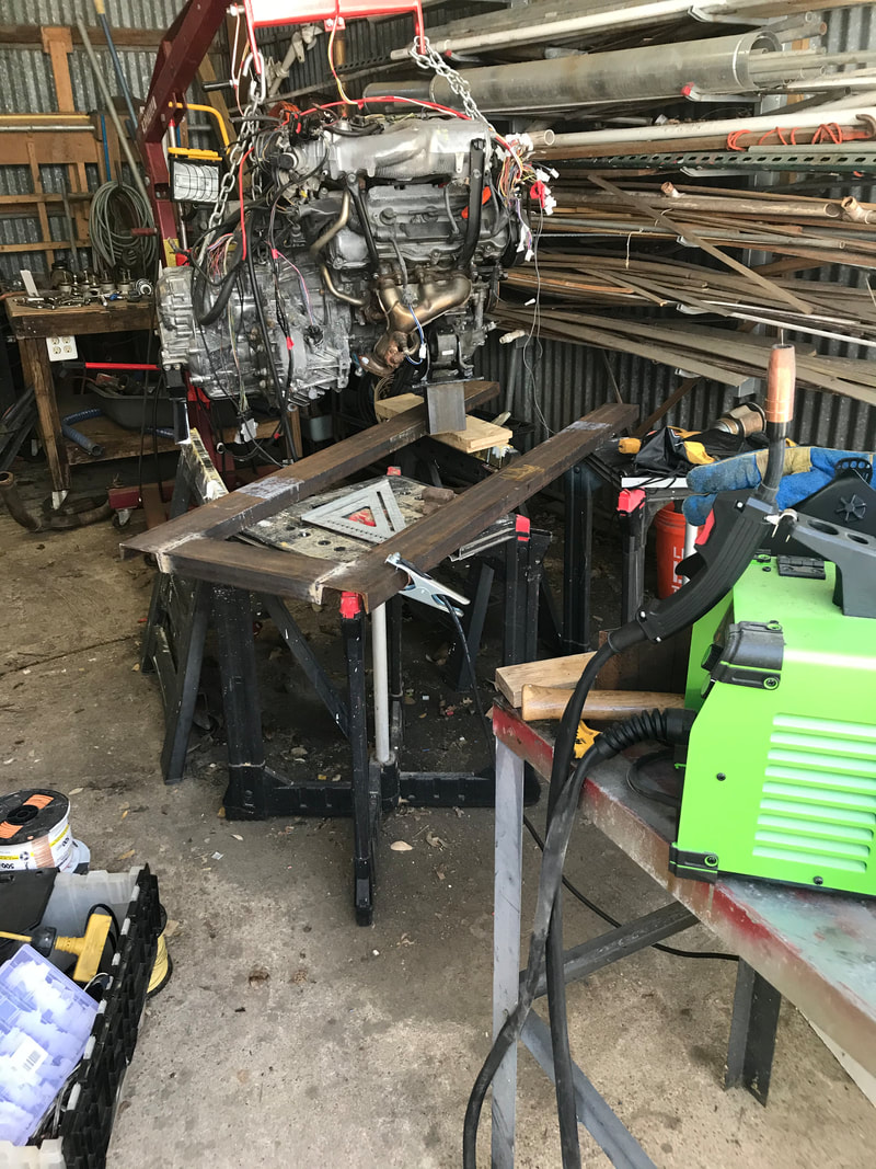
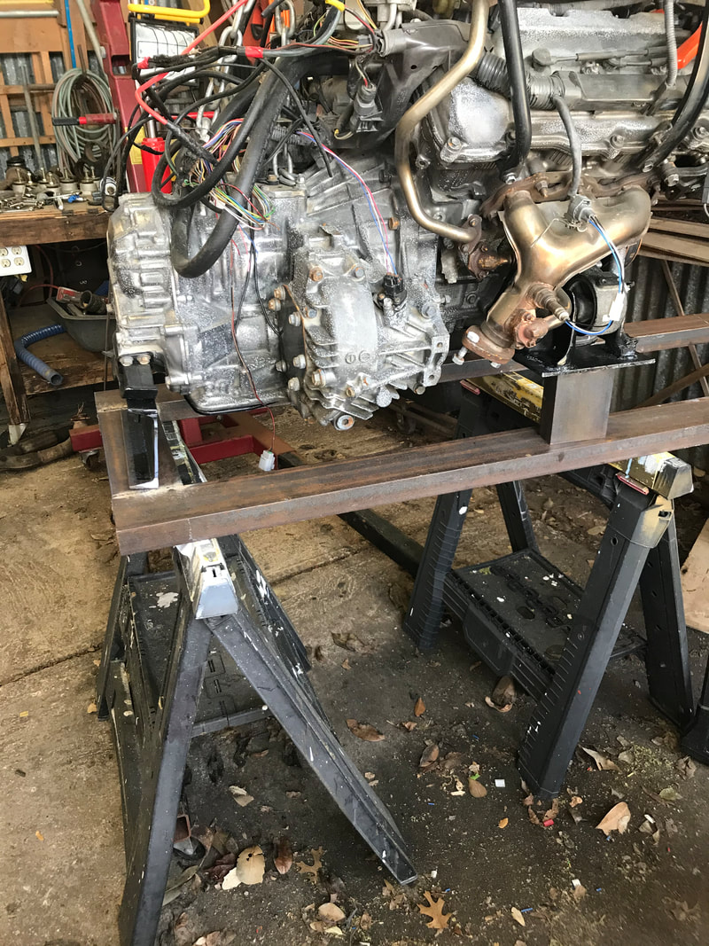
08/08/2021 Using engine hoist, I lifted frame and placed sawhorses for support. As I get older, my body does not like it when I bend over for too long. I also used metal clamps to hold brace that needed to be restored, in prep for re-welding. I made sure frame was level and square.
|
|
08/05/2021
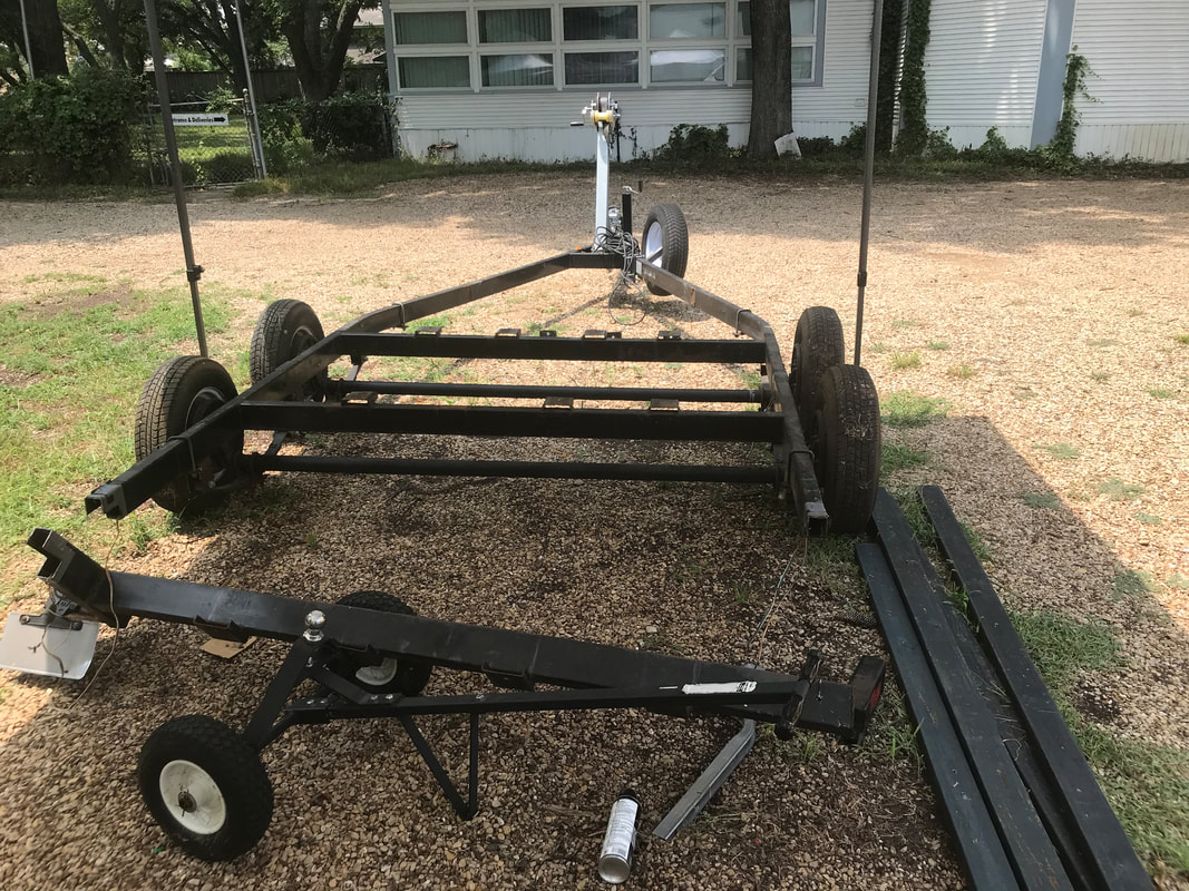
Began working on extending the trailer. Cut off all side braces and removed all bottom bunks. Plan to use roller bunks to ease unloading boat into water. Cut off rear end of trailer and plan to add 10' 2x4 steel tubes inserts. Loosened L-bracket that holds tandem axles and moved forward to give clearance to work and believe will have to move back over joint welds of frame addition to get proper balance for trailer and boat.
Began working on extending the trailer. Cut off all side braces and removed all bottom bunks. Plan to use roller bunks to ease unloading boat into water. Cut off rear end of trailer and plan to add 10' 2x4 steel tubes inserts. Loosened L-bracket that holds tandem axles and moved forward to give clearance to work and believe will have to move back over joint welds of frame addition to get proper balance for trailer and boat.
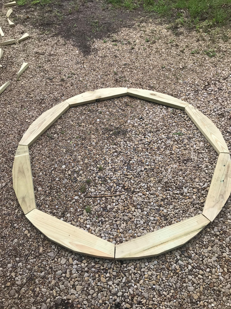
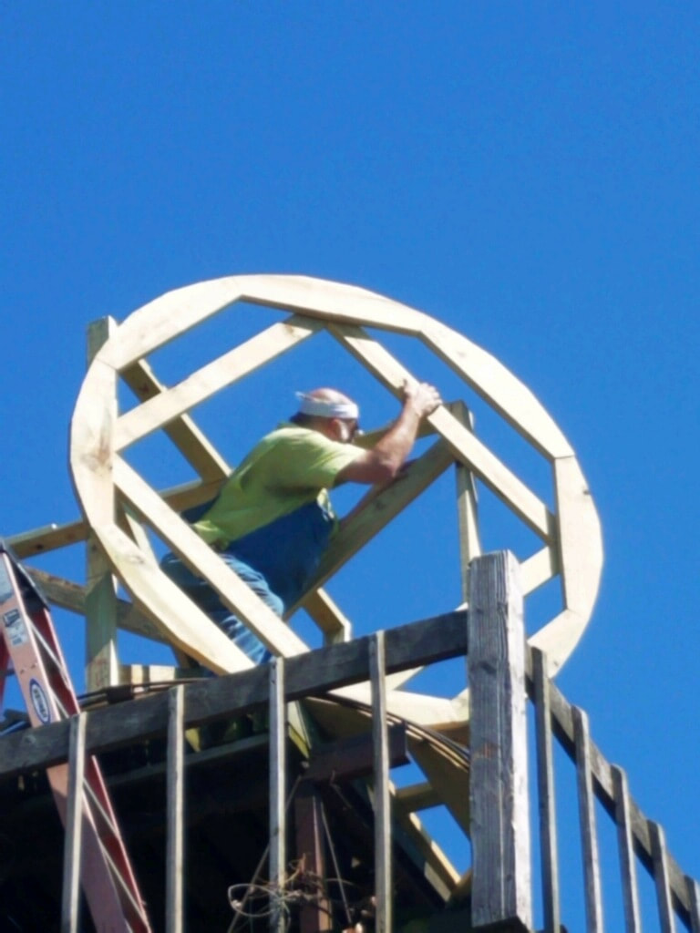
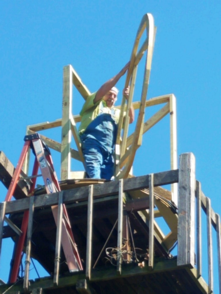
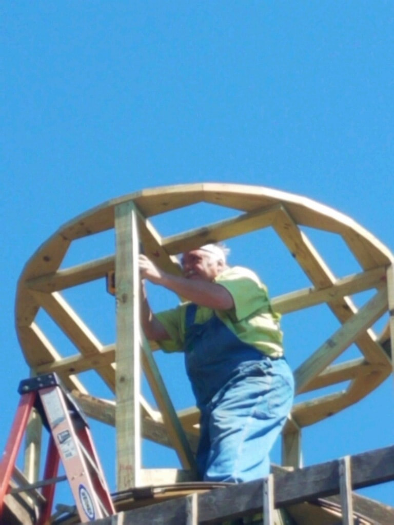
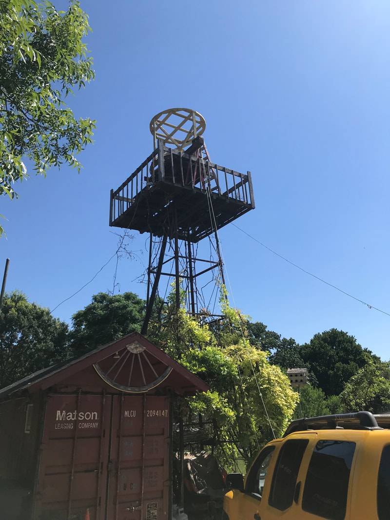
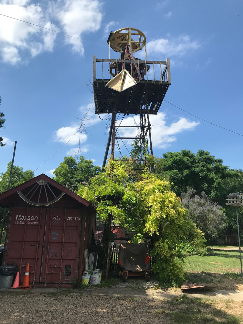
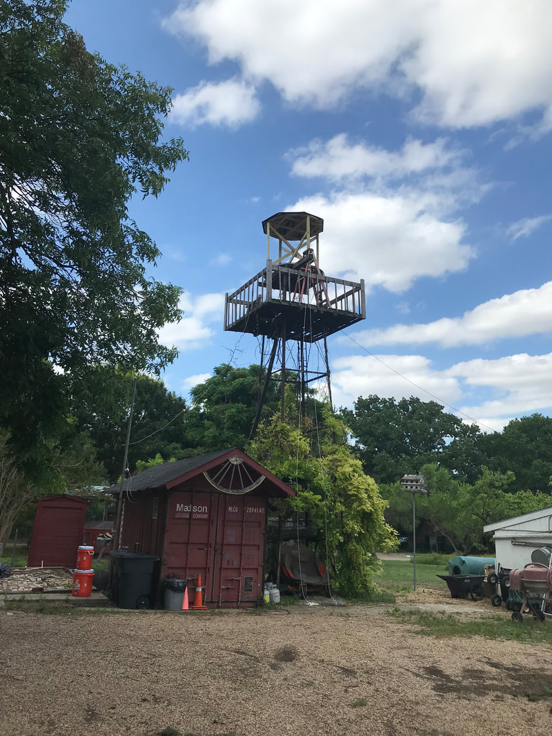
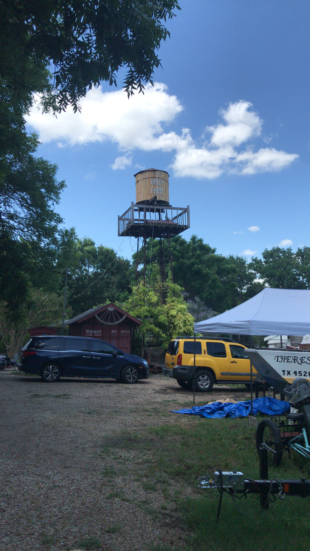
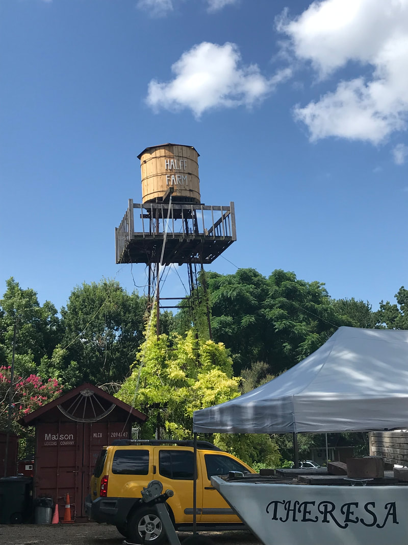
06/22/2021 On a farm there are always extra projects that need to be done. Lost power to the house, when a limb took out the power line from the pole to the house. Was told needed to clear a path for line, before they reinstall it. Cut 5 trees down with some friends. After power restored, decided to have more trees removed professionally, which really exposed my water tower to public view. This pushed the replacement of the tower tank project to the fore front. Plan is to remove 550 gal. tank from up top tower and replace with a wooden fake tank. Tower is over 100 years old, and I figured would not be able to bear the 4,500 lbs a full 550 gal. tank would weigh, if I used the tank.


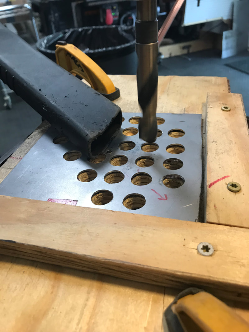
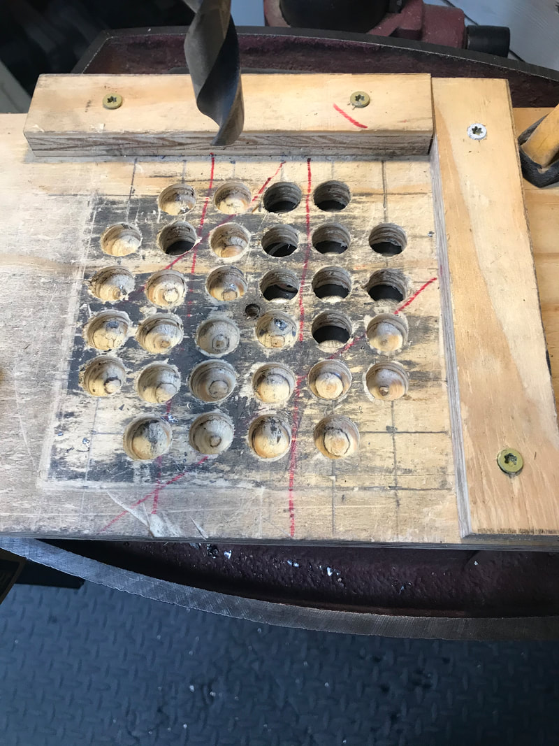
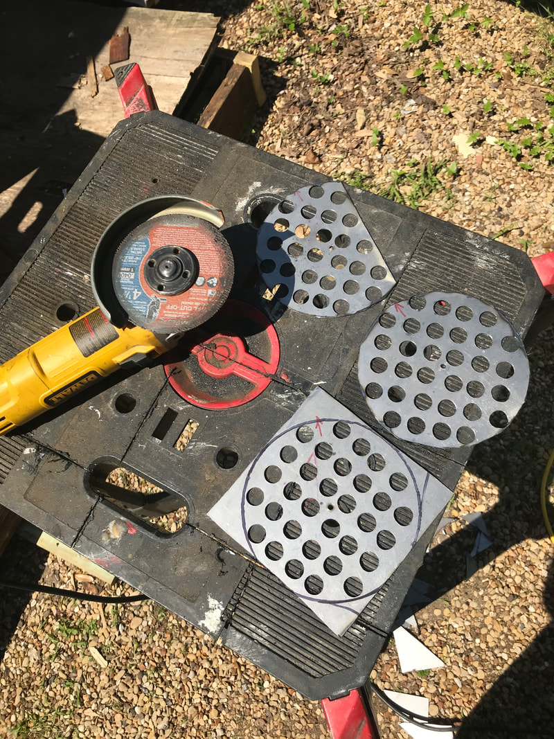
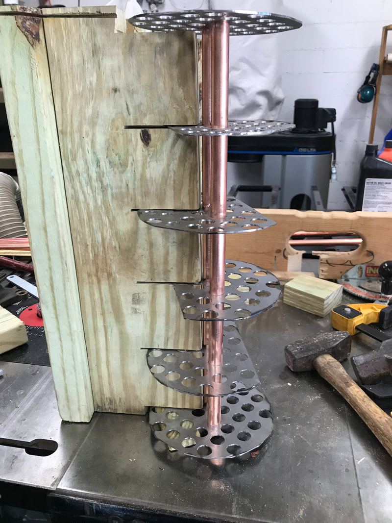
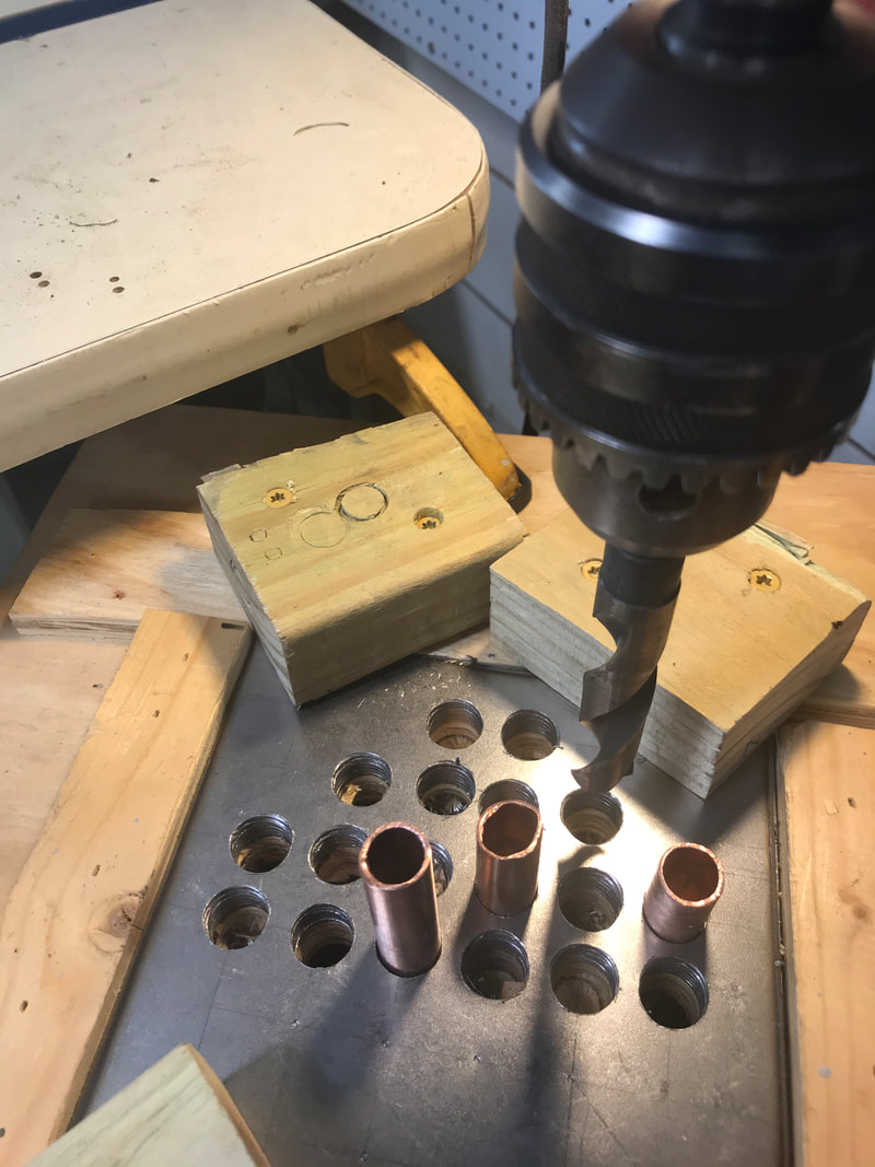
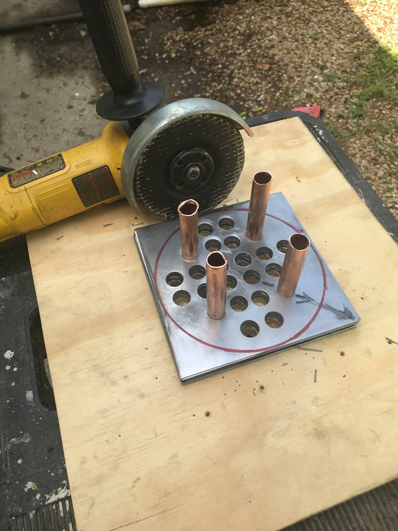
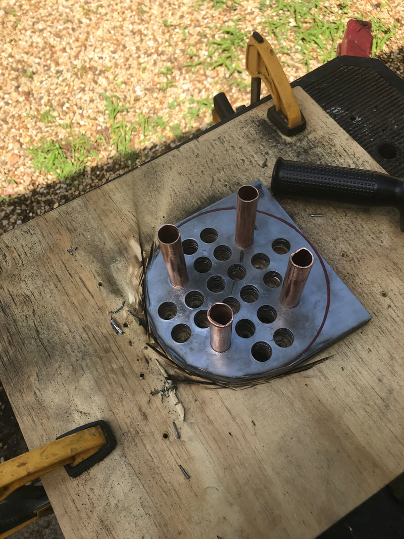
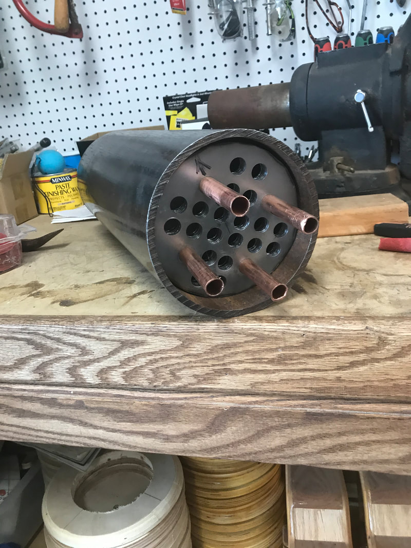
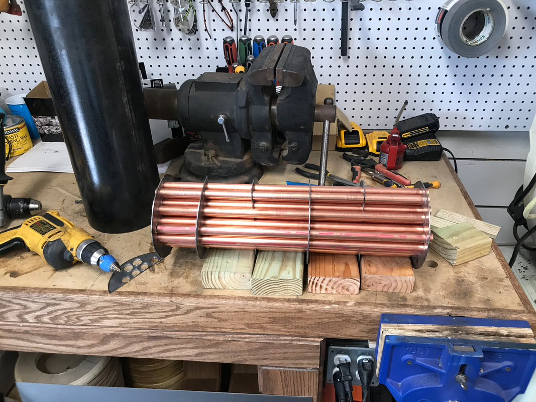
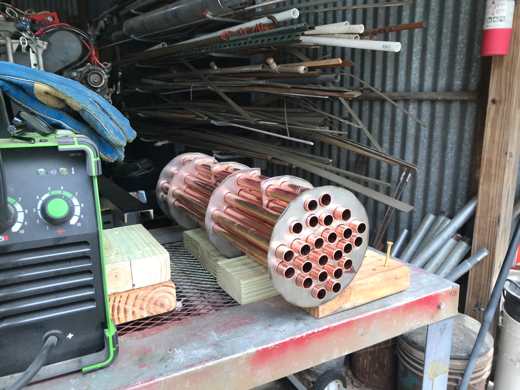
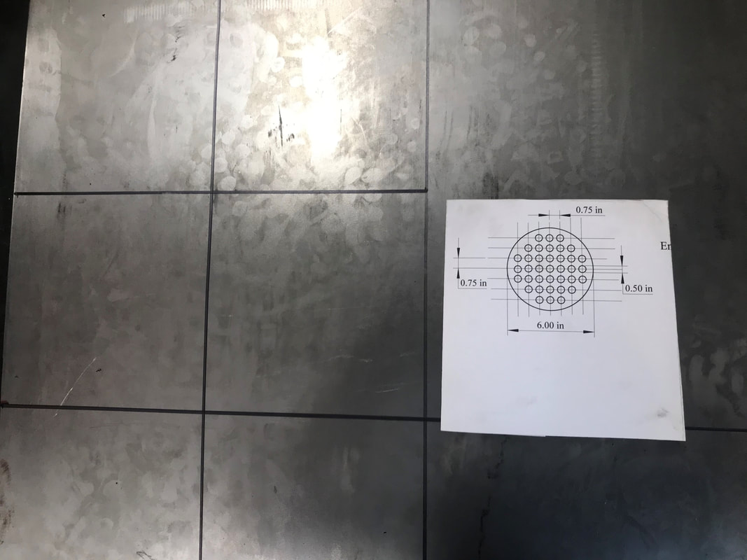
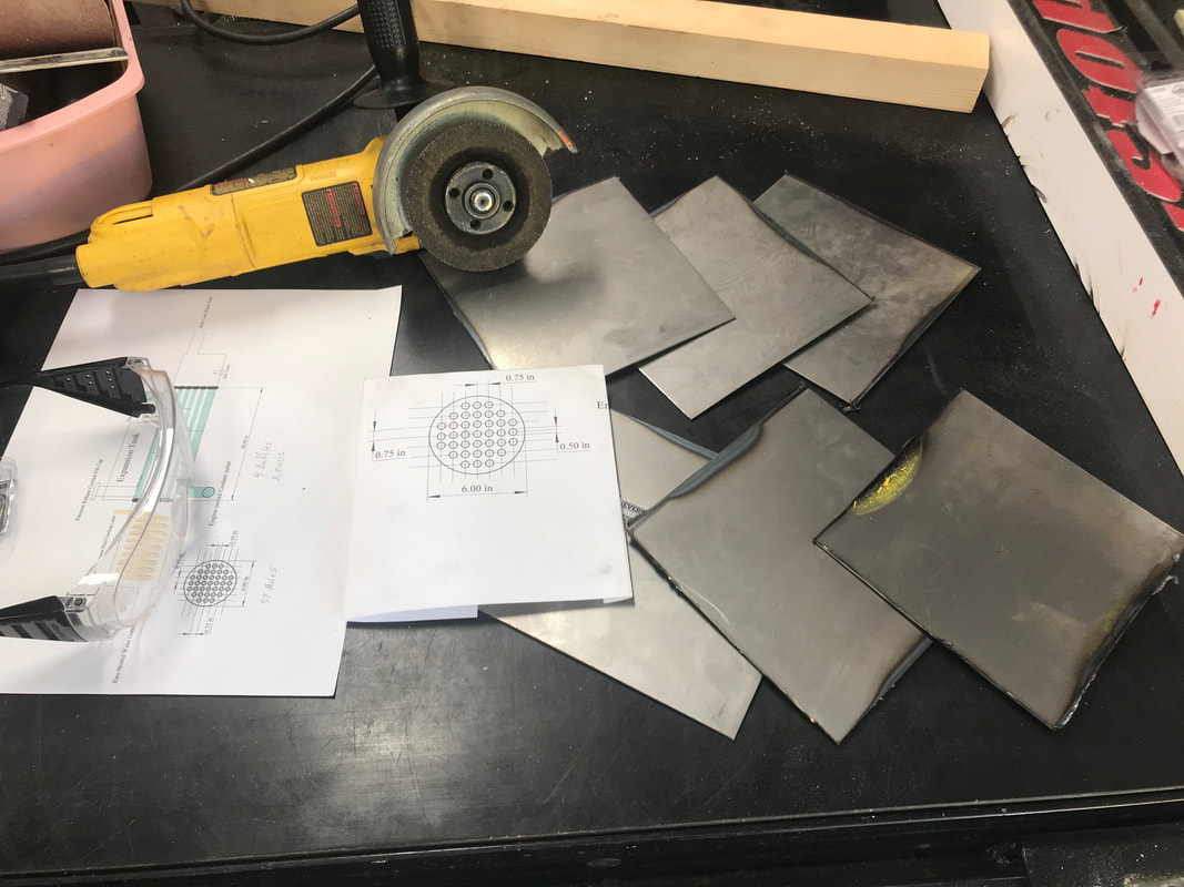
04/26/2021 Whaaa! Not sure if I am to old to be allowed to say whaaa, but "Whaaa!" anyways. Have spent the past week making the ends and baffles for the heat exchanger. First I drilled all the holes, only to find the 1/2" drilled holes were too small. Yes I was using 1/2" pipes, but that is the inner diameter. I need to drill 5/8" holes, and so I need to redesign with proper spacing and cut more blanks. Drilled all the holes again, only to find since I did each plate separately, the holes did not line up to well. So made blanks again and and stacked plates together and drilled all holes at same time, holes now lined up, but still a very tight fit. Found a step drill bit was all I need to enlarge the holes, which worked perfectly. Was able to assemble inner pipe assembly for exchanger and begin welding together. Now here comes the Whaaa! The welder melted holes in the copper pipes and now can not take apart to replace copper pipes. So going to begin again, but using 11/16 drill bit, and this time solder the pipes onto the plates. Wish me luck!
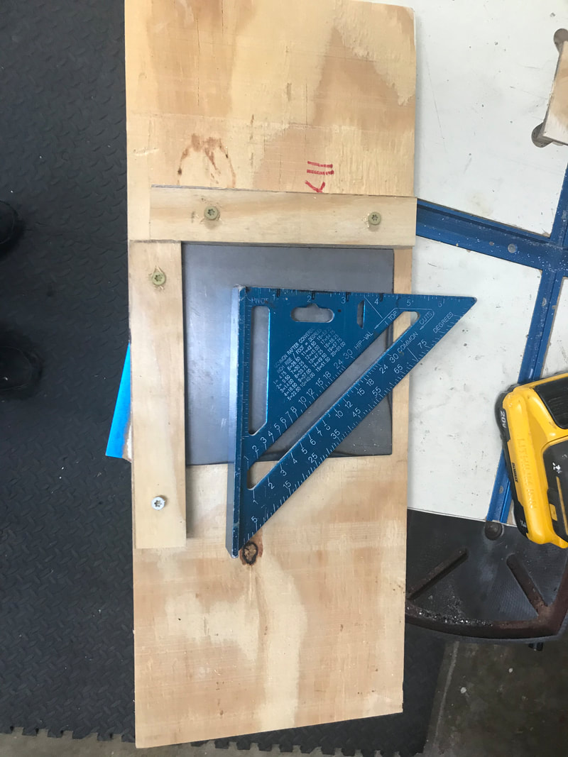
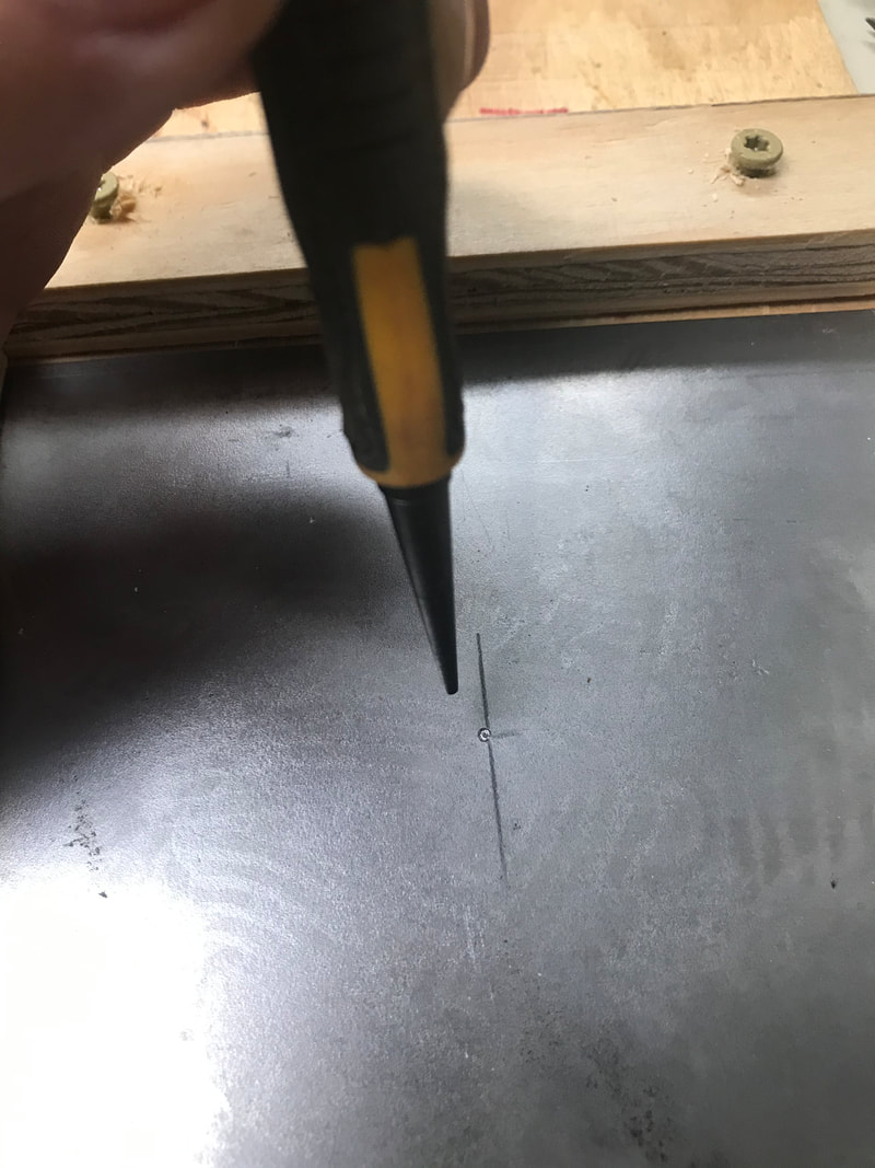
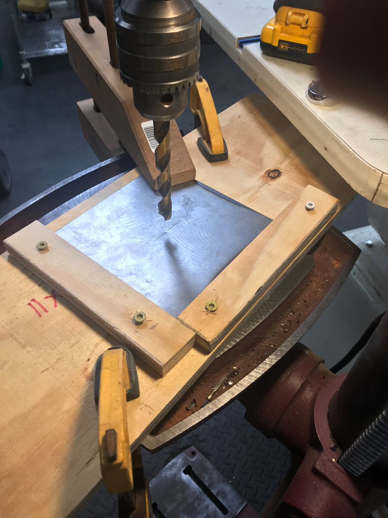

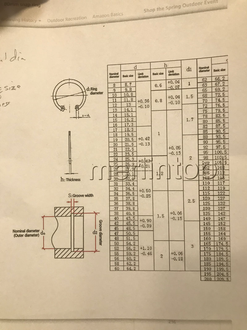
04/17/2021 Retaining ring may have been for the vehicle that engine came from, but apparently not for the location. Learned some things about the snap ring. Ordered snap ring by looking at a chart, which required taking several measurements. Also was able to cut a sheet into blanks, which I hope to drill to become the ends and baffles for the heat exchanger.
|
|
04/15/2021 So excited, the shaft retaining snap ring came in today. Went to install it, only to realize I need to remove the shaft to slip it over the end that goes into the transmission. I had worked so hard to pound that shaft in, I really was not looking forward to doing it again. After forcing the shaft out, I saw that the bolts holding the bearing and support bracket were only hand tightened, and that the bracket was never flush against the engine. Once properly tightened, the shaft went in more easily. Now to squeeze the ring's to end together so it can be placed in the channel, but concentrating to keep the pliers in correct alignment and with enough force to squeeze, I never had enough to maneuver the ring into the channel. So now waiting for the proper tool to be delivered (I had went to store to see if I could find one.) Was able to buy more materials for the heat exchanger.
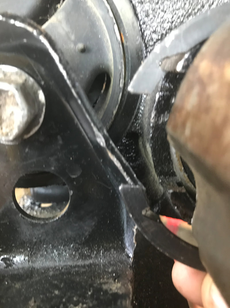
Need a tool to fit in the gaps and pull the ends together.
04/14/2021
I know I already made an entry today, but it was getting longer as I added stuff. So decided to break it up a bit.
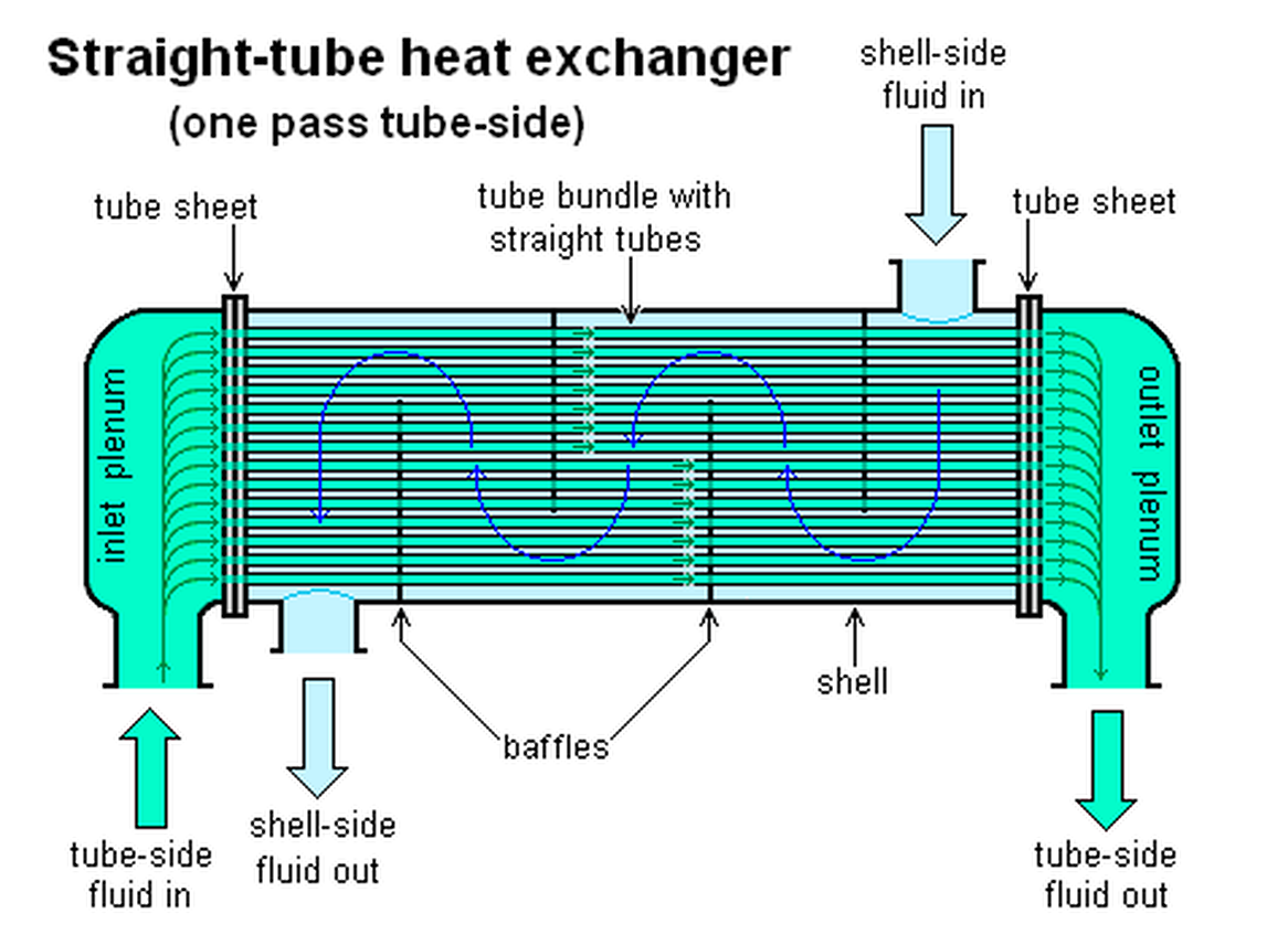
Made my first rough draft of the proposed heat exchanger. Took a bit of investigation to figure where the expansion tank hook into, into the coolant side, just like it does on the radiator. Also found that there are baffles on the tubes to force the coolants to flow over the tubes multiple times. Those are the thin dividers in the picture with the cut-out. Also since the cooling water is not under great pressure, the ends of the heat exchanger are made to be removable for cleaning I assume.
I know I already made an entry today, but it was getting longer as I added stuff. So decided to break it up a bit.
Made my first rough draft of the proposed heat exchanger. Took a bit of investigation to figure where the expansion tank hook into, into the coolant side, just like it does on the radiator. Also found that there are baffles on the tubes to force the coolants to flow over the tubes multiple times. Those are the thin dividers in the picture with the cut-out. Also since the cooling water is not under great pressure, the ends of the heat exchanger are made to be removable for cleaning I assume.
Another picture I found on the web
4/14/2021
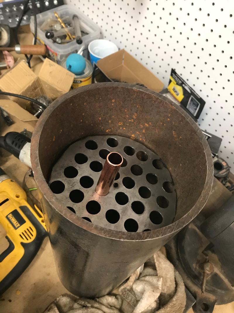
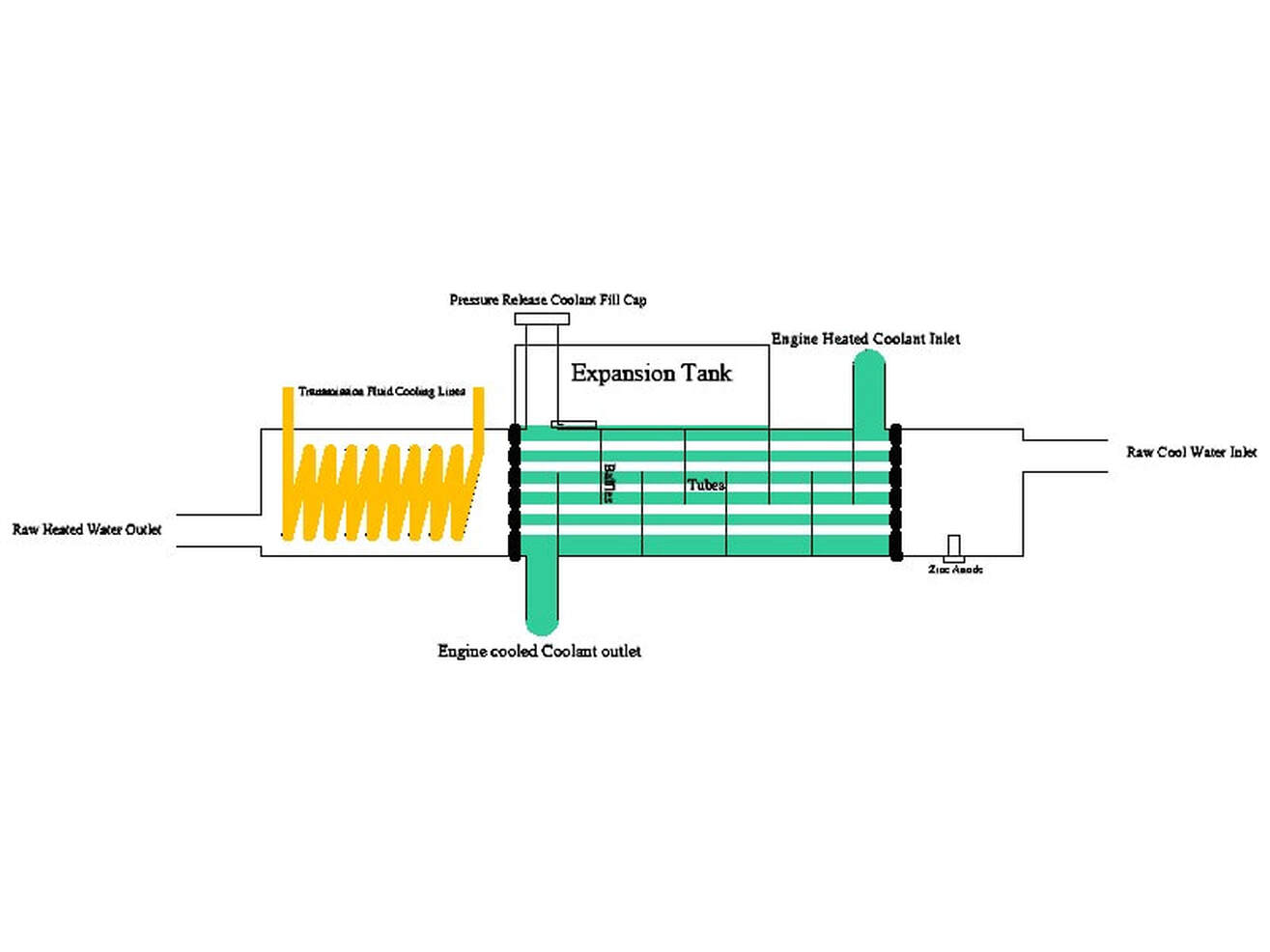
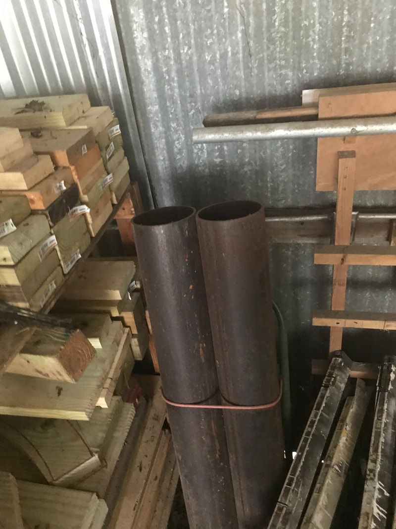
Not sure if I want to pay the high dollar amount (around $2000) for a ready built heat exchanger or design my own. If I design my own, think will go ahead and run the transmission line inside as well, to get a two for one deal. Been looking at pictures and the idea is raw water enters into first chamber then goes through tubes passing through second chamber, and then into third chamber where it is pumped over-board or used else where. First chamber contains a pressure capped fill tube, which is also connected to an expansion tank, and last but not least, the sacrificial zinc anode (more on this part later). Second chamber is where heated coolant (water and antifreeze) from engine enters, flows between raw water tubes and gives up heat, there by cooling, and is sucked out via engine circulating pump. Third chamber is where heated raw water flows out of the heat exchanger. I may divide the second chamber into chamber A for engine coolant, and chamber B for the transmission fluid. Went looking to see if I had any readily available materials to even make the heat exchanger, and guess what, found I had 6" dia pipe left over from a church safety bollard project (set like post, filled with cement, to prevent someone from driving into the church via the entrance.)
Not sure if I want to pay the high dollar amount (around $2000) for a ready built heat exchanger or design my own. If I design my own, think will go ahead and run the transmission line inside as well, to get a two for one deal. Been looking at pictures and the idea is raw water enters into first chamber then goes through tubes passing through second chamber, and then into third chamber where it is pumped over-board or used else where. First chamber contains a pressure capped fill tube, which is also connected to an expansion tank, and last but not least, the sacrificial zinc anode (more on this part later). Second chamber is where heated coolant (water and antifreeze) from engine enters, flows between raw water tubes and gives up heat, there by cooling, and is sucked out via engine circulating pump. Third chamber is where heated raw water flows out of the heat exchanger. I may divide the second chamber into chamber A for engine coolant, and chamber B for the transmission fluid. Went looking to see if I had any readily available materials to even make the heat exchanger, and guess what, found I had 6" dia pipe left over from a church safety bollard project (set like post, filled with cement, to prevent someone from driving into the church via the entrance.)
Here is an article about the sacrificial anode.
What Is a Sacrificial Anode
Written by admin in Response Post,Water Education,Water Sports & Recreation
There are many important parts of a boat that all have some function that they perform. One of the most important parts is the Sacrificial Anode. It helps all other parts function protecting them from corrosion. what is a sacrificial anode?
A Sacrificial Anode is an Anode made from a less noble metal like aluminum or zinc. More electrically active, it protects the other two Metal Anodes when connected to them in seawater to make a circuit, & gives up its electrons, dissolving first while preventing Galvanic Corrosion on boat parts.
Easily missed by most people but a necessity for all sailors and boat owners to know about for the ultimate protection of their vessel. Here’s Why.
What Is Galvanic CorrosionAll metals immersed in an electrolyte sea water, for example, produce an electrical voltage. When two dissimilar metals are in contact or electrically connected then they produce a galvanic cell turning them into a battery, with the less noble metal for an example, a bronze propeller, on the boat, forming the anode and the more noble metal say a stainless steel shaft forming the cathode. Remember the cathode attracts cations or the cathode attracts (positive) + charge. The anode attracts (negative) – charge, creating a circuit.
One of the metals is constantly taking a beating and giving pieces of itself up as the current is existing uninterrupted. These pieces are called metal ions, used in order to make electrons that are needed for making an electric current. The process of a metal deteriorating over time due to electrical activity is known as Galvanic Corrosion, and on a boat, it can lead to some serious problems.
The most common places for galvanic corrosion to occur on a boat are on the propeller that is usually made of bronze or aluminum, the prop shaft, rudders, sterndrives or outboard. If Galvanic Corrosion is not controlled, it can end up costing a boat owner a ton of money in damages, repairs, and even replacements.
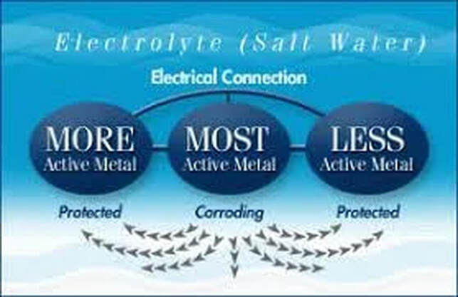
In order to protect both metals, you need to connect a third metal that is more active than the first two. The most active metal zinc, for example, becomes the anode to the others and sacrifices itself by corroding giving up metal ions in order to protect the cathode hence the term sacrificial anode.
|
This Galvanic Corrosion at work where one metal either a (anode or cathode), makes a connection with another metal in Salt Water which is an Electrolyte solution that makes an Electrical current. Electrons are used in the process deteriorating and destroying the anode that has more electrical potential eventually destroying metal parts under your boat.
To stop this from happening, the solution is to add a third metal to the equation in between the connection of electrical current. By doing this you sacrifice the important metals metals that are involved with the boat by giving themselves up. The Sacrifice Metal has to be more active than the other two. This metal becomes the Anode that is used by the other pair. |
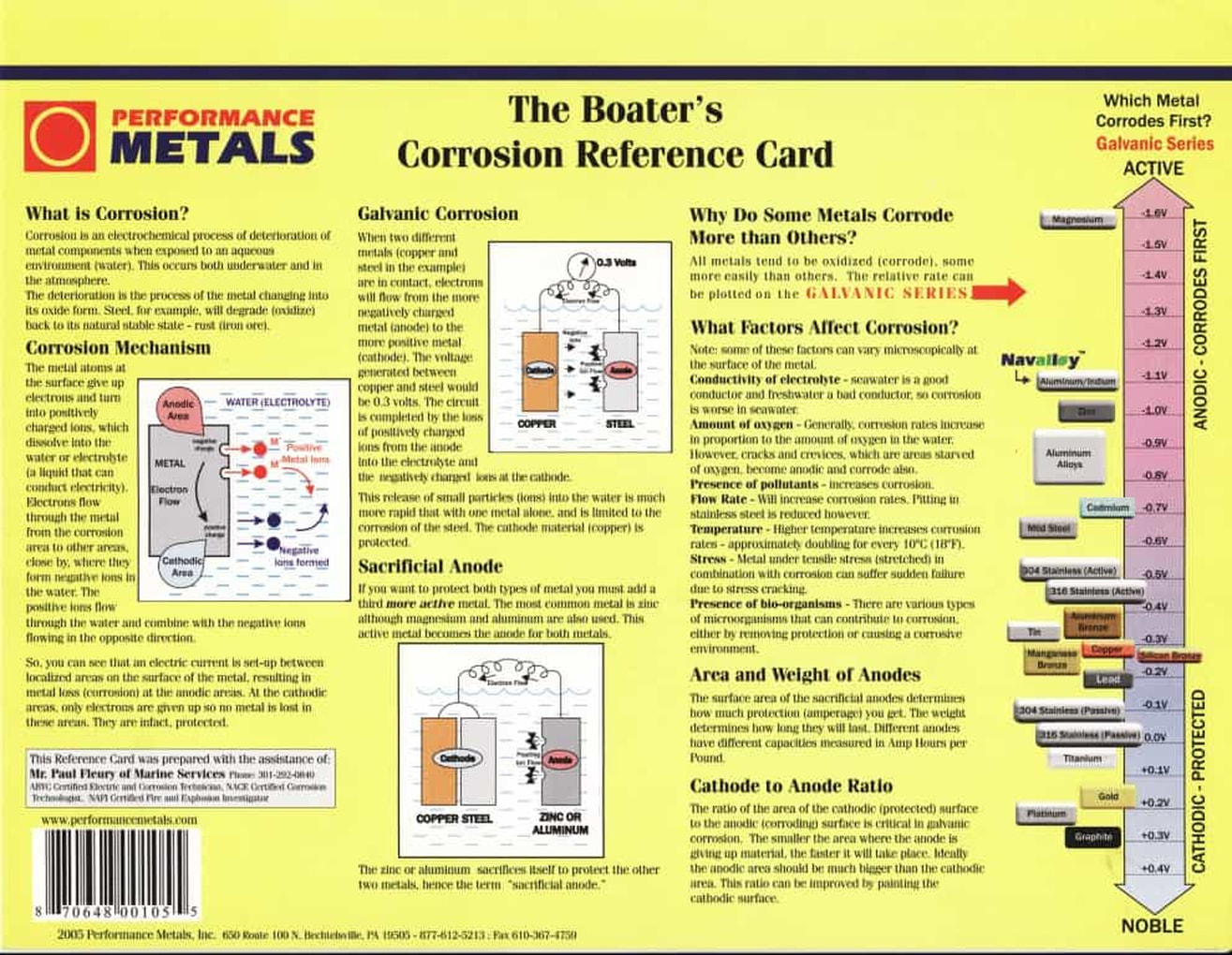
The three most Active materials that are used in Sacrificial Anodes are zinc, aluminum, and magnesium. The first property to consider is its electrical potential. All metals generate a negative voltage (as compared to a reference electrode) when immersed in water. The lower – the more negative – the voltage, the more active the metal is considered to be, for example:
Magnesium generates -1.6 Volts, i.e. negative 1.6 volts.
Aluminum sacrificial anode alloy generates -1.1Volts
Zinc, -1.05 Volts
In order to provide protection, the highest practicable voltage difference possible is required between the sacrificial anode and the metal to be protected.
For example, if zinc anode is used to protect a bronze propeller, a “driving or protecting voltage” of negative –0.75 volts will be available, i.e. zinc at -1.05 volts minus bronze at -0.3 = – 0.75 volts.
If aluminum anodes are used this increases to -0.8 Volts.
Magnesium anodes increase this to -1.3 volts.
The bigger the difference in voltage, the more protection you get.
How does a sacrificial anode work? Aluminum Alloy Anodes Are used on boats that travel in Brackish water. They are or recommended for use on boats that are used in Salty water or Freshwater. They can generate 1.1 volts.
Magnesium Alloy Anodes are recommended and work well in the freshwater environment and are not recommended for Saltwater at all.
Sacrificial Anodes and Zincs- These type Anodes are made to sacrifice themselves to the electrical current so you’re boat parts won’t have to. Sacrificial Anodes are typically made from zinc because it’s the best alloy that protects boats in the ocean. This is why Sacrificial Anodes are quite often referred
Sacrificial Anodes have a working life to them and will wear down and eventually be of no use leaving the boat owner at risk for damage to their boat. They also have to be installed the right way or the same bad result will happen
Besides the Electrical Potential, the next factor most important in Sacrificial Anodes is the Current Capacity of the anode material. The anode generates a voltage difference and this drives a current between the anode and the protected metal and through the water. The 3rd factor is Quality and that just means that you are getting what you are paying for. The most common material specs to look for are:
Inboard boats with bronze or stainless metal parts can be protected using Zinc or Aluminum Anodes. Don’t worry about overkill from overprotecting. It doesn’t matter. The voltage added by Zinc or Aluminum won’t cause any damage. No matter how much anode material is added the maximum voltage won’t change. It will stay the voltage generated by the anode itself.
Sterndrives and Outboard Motors
Can require a little more care. The sacrificial anodes have a difficult task since they have to protect what is already a very active aluminum assembly. Initially, the anodes for these units were made of zinc, but in response to corrosion problems, Mercury and Johnson/Evinrude/OMC started selling the aluminum anodes in the early 1990s.
Other manufacturers are switching to aluminum too. The small increase in protective voltage helps ensure that the sterndrive is protected. If you use zinc anodes you may even invalidate your warranty! Again, be careful using magnesium anodes since you can overprotect your sterndrive or outboard.
Keep paint on Sterndrives and engines in good condition and keep Sterndrive immersed in water. If you don’t then the Anodes won’t be able to work. Don’t mix zinc anodes on the hull with aluminum anodes on the drive. The aluminum anodes will protect the zinc anodes in addition to the unit.
Where possible Navalloy™ is a combination of (aluminum/zinc/indium alloy) these anodes are recommended over zinc. Zinc anodes can become inactive after only a few months due to the build-up of an insulating film of zinc hydroxide. Aluminum anodes will remain active. ABYC (American Boat and Yacht Council), who set the standards for the industry, clarified their recommendations on anode materials in the Standards and Technical Information Reports for Small Craft (July 2008-2009):
How to Install Anodes On a Boat
For Sacrificial Anodes to be effective they have to be installed in the direct vicinity and as close to the metal that it is meant to be protected as possible. Metal to metal is the best option. To do this, mount the Anode itself to the metal that needs to be protected. You can also direct the two by using a wire.
It’s important that the surface of the metal is clean when you mount the Anode to it. This ensures the best electrical contact is made.
When using Sacrificial anodes, you have to be sure that you don’t use too much or too little for total protection. Most boaters agree that 1-2% coverage of the surface area of the metal to be protected must be covered.
If you use too much zinc to protect your metal, it can crust over and stop working completely. Be sure that you are not over or under using your anode!
Sacrificial Anodes should be replaced once a year or when they are corroded to half their size. Premium Anodes have a Red Spot marker that will show when it’s time to replace them.
Never paint over an Anode. If they are cover-up they won’t work.
Boat Parts at Risk of Galvanic Corrosion
Magnesium generates -1.6 Volts, i.e. negative 1.6 volts.
Aluminum sacrificial anode alloy generates -1.1Volts
Zinc, -1.05 Volts
In order to provide protection, the highest practicable voltage difference possible is required between the sacrificial anode and the metal to be protected.
For example, if zinc anode is used to protect a bronze propeller, a “driving or protecting voltage” of negative –0.75 volts will be available, i.e. zinc at -1.05 volts minus bronze at -0.3 = – 0.75 volts.
If aluminum anodes are used this increases to -0.8 Volts.
Magnesium anodes increase this to -1.3 volts.
The bigger the difference in voltage, the more protection you get.
How does a sacrificial anode work? Aluminum Alloy Anodes Are used on boats that travel in Brackish water. They are or recommended for use on boats that are used in Salty water or Freshwater. They can generate 1.1 volts.
Magnesium Alloy Anodes are recommended and work well in the freshwater environment and are not recommended for Saltwater at all.
Sacrificial Anodes and Zincs- These type Anodes are made to sacrifice themselves to the electrical current so you’re boat parts won’t have to. Sacrificial Anodes are typically made from zinc because it’s the best alloy that protects boats in the ocean. This is why Sacrificial Anodes are quite often referred
Sacrificial Anodes have a working life to them and will wear down and eventually be of no use leaving the boat owner at risk for damage to their boat. They also have to be installed the right way or the same bad result will happen
Besides the Electrical Potential, the next factor most important in Sacrificial Anodes is the Current Capacity of the anode material. The anode generates a voltage difference and this drives a current between the anode and the protected metal and through the water. The 3rd factor is Quality and that just means that you are getting what you are paying for. The most common material specs to look for are:
- Zinc: MIL-A-18001K
- Aluminum: MIL-A-24779(SH)
- Magnesium: MIL-A-21412
Inboard boats with bronze or stainless metal parts can be protected using Zinc or Aluminum Anodes. Don’t worry about overkill from overprotecting. It doesn’t matter. The voltage added by Zinc or Aluminum won’t cause any damage. No matter how much anode material is added the maximum voltage won’t change. It will stay the voltage generated by the anode itself.
Sterndrives and Outboard Motors
Can require a little more care. The sacrificial anodes have a difficult task since they have to protect what is already a very active aluminum assembly. Initially, the anodes for these units were made of zinc, but in response to corrosion problems, Mercury and Johnson/Evinrude/OMC started selling the aluminum anodes in the early 1990s.
Other manufacturers are switching to aluminum too. The small increase in protective voltage helps ensure that the sterndrive is protected. If you use zinc anodes you may even invalidate your warranty! Again, be careful using magnesium anodes since you can overprotect your sterndrive or outboard.
Keep paint on Sterndrives and engines in good condition and keep Sterndrive immersed in water. If you don’t then the Anodes won’t be able to work. Don’t mix zinc anodes on the hull with aluminum anodes on the drive. The aluminum anodes will protect the zinc anodes in addition to the unit.
Where possible Navalloy™ is a combination of (aluminum/zinc/indium alloy) these anodes are recommended over zinc. Zinc anodes can become inactive after only a few months due to the build-up of an insulating film of zinc hydroxide. Aluminum anodes will remain active. ABYC (American Boat and Yacht Council), who set the standards for the industry, clarified their recommendations on anode materials in the Standards and Technical Information Reports for Small Craft (July 2008-2009):
How to Install Anodes On a Boat
For Sacrificial Anodes to be effective they have to be installed in the direct vicinity and as close to the metal that it is meant to be protected as possible. Metal to metal is the best option. To do this, mount the Anode itself to the metal that needs to be protected. You can also direct the two by using a wire.
It’s important that the surface of the metal is clean when you mount the Anode to it. This ensures the best electrical contact is made.
When using Sacrificial anodes, you have to be sure that you don’t use too much or too little for total protection. Most boaters agree that 1-2% coverage of the surface area of the metal to be protected must be covered.
If you use too much zinc to protect your metal, it can crust over and stop working completely. Be sure that you are not over or under using your anode!
Sacrificial Anodes should be replaced once a year or when they are corroded to half their size. Premium Anodes have a Red Spot marker that will show when it’s time to replace them.
Never paint over an Anode. If they are cover-up they won’t work.
Boat Parts at Risk of Galvanic Corrosion
- Propellers and Rudders- protected typically by Zinc
- Hull Plates-Multiple Zinc Plates
- Outdrives- Multiple Anodes are used for protection
- Heat Exchangers- preemptively fitted with a zinc “pencil” anode. They are usually installed beneath a brass plug in the exchanger.
The advantage of Sacrificial Anode systems over others is they need no external power source, are easy to install, the low voltage and current between the anode and the surface it is protecting infrequently generate stray current, overprotection is unlikely, and inspection and monitoring is simple if you know what to look for. To protect your investment.
Oxidation wears out metal parts frequently, causing them to deteriorate faster rates if they are not protected by a Sacrificial Anode. Saltwater contains electrolytes that create an electrically conductive solution. When metal parts from your boat are introduced into this solution, such as iron, bronze or aluminum like the hulls, ship propellers, outboard engines of a boat, they wouldn’t last very long.
Oxidation wears out metal parts frequently, causing them to deteriorate faster rates if they are not protected by a Sacrificial Anode. Saltwater contains electrolytes that create an electrically conductive solution. When metal parts from your boat are introduced into this solution, such as iron, bronze or aluminum like the hulls, ship propellers, outboard engines of a boat, they wouldn’t last very long.
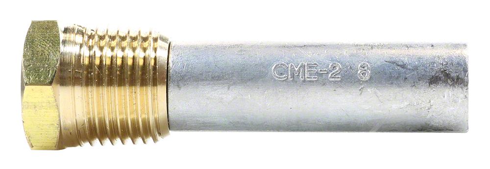
The sacrificial zinc anode
04/13/2021
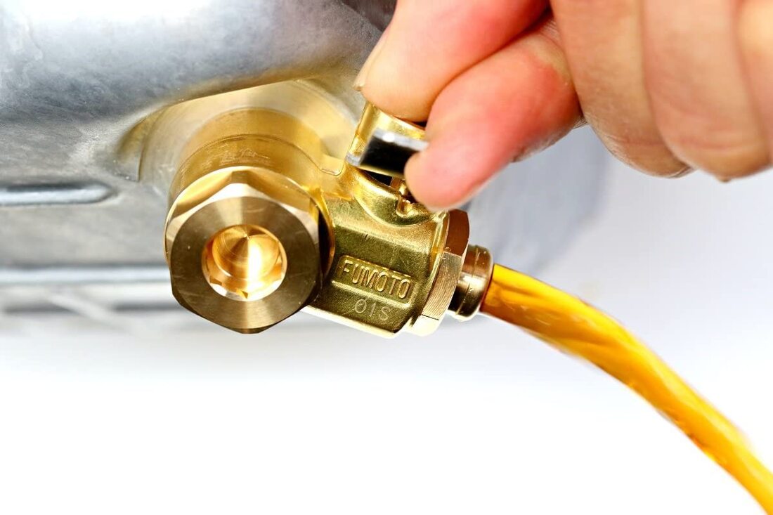
Was planing to use either aluminum or copper tubing to extend the oil drain to a cut off valve and then through the hull bottom. I believe the Lord has me procrastinate for a reason. Hating to postpone the project till parts arrive for the drive shaft before going to next step, I started preparing to find the parts needed for the drain extension. While searching, I had a vision of the motor vibrating, which is the reason for the rubber mounts and the shock absorbed, when I realized, that a solid non-flexing tube would get damaged. The motor being metric, I had to fine a drain valve for a 12 mm opening.
Found F103SX: New Generation Fumoto Valve with 12mm-1.25 Thread Size will do the job nicely.
Been trying to get all the systems that will be placed on the engine frame, started before placing said frame withing the boat. Need to figure out a cooling system for the engine to replace the radiator. Possibly a heat exchanger, which cools via lake water, to cool a closed system going through the engine. Also have to have a cooling system for the transmission fluid. Same system can be used to cool exhaust as well.
Found an article of interest.
Inboard Engine Cooling SystemsModern cooling systems with heat-exchangers work with advanced coolants, but still need old-fashioned maintenance to stay efficient.
By Ed Sherman
February 21, 2017
In the old days, many marine engine cooling systems were of the “raw-water” variety, meaning simply that they relied on pumping whatever water the boat was floating in through the engine and pumping it out the exhaust system—salt water, polluted water, algae-infested water, whatever was available. The impact this had on the longevity of the engines was profound, especially in the extra-corrosive saltwater world.
So as time went on, engine manufacturers began supplying more and more “freshwater-cooled” or “closed-system” engines using antifreeze/coolant internal to the engine, but cooling it with raw water from outside the boat via a heat exchanger.
Think of the heat exchanger on your boat engine as the radiator on your car: They play the same role in shedding heat away from the closed side of the system.
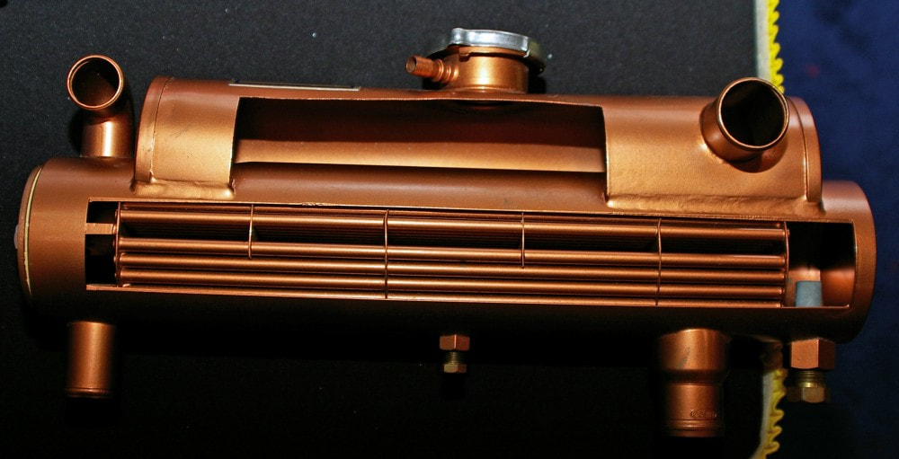
A cutaway view of this heat exchanger shows cooling tubes, expansion tank, pressure cap, and sacrificial zinc anode on the lower right.
Besides exposure to corrosive materials in the water, raw-water cooled engines suffered from another major drawback. They had a thermostat, just like all engines, but it was regulated at 145-150° F. This was done to minimize the possibility that salt in the salt water would separate out and crystallize inside the engine’s cooling passages, with 160°F being the critical turning point for this to occur. This comparatively cool running temperature limited the engine’s ability to reach a maximum level of thermal efficiency, which in turn had a negative impact on fuel economy and to some degree overall engine longevity. The cooler temperatures also caused varnish and gum buildup inside the engine, which ultimately contributed to other problems.
The trick with any engine is to get it running as hot as it can run without causing any damage. That’s when you know it’s running at peak efficiency, assuming proper fuel and exhaust system design. Consider a modern automobile that will typically run at 215° F. It is undoubtedly getting much better mileage than its 15-year-old counterpart.
Today almost all new marine engines use the closed cooling system design. These systems are pressurized, just like your car or truck. By increasing the pressure inside the closed part of the system, the boiling point of the coolant is enhanced. For every pound of pressure added, approximately 3° F can be added to your engine’s operating temperature, improving its thermal efficiency. Increased pressurization and advanced engine metallurgy have driven the folks who design and make what today must be referred to as engine coolant versus mere “antifreeze” to come up with some very sophisticated chemical formulas.
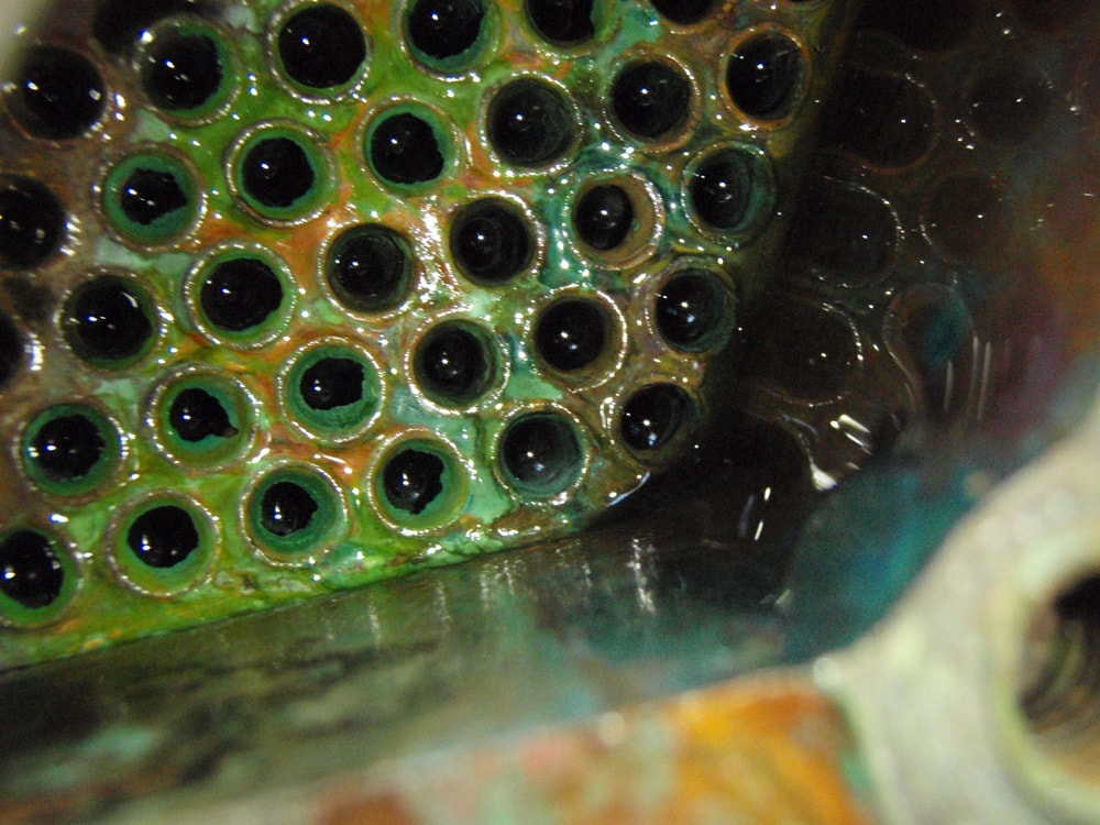
Inside the raw-water side of the heat exchanger, calcium-lime deposits will build up and reduce engine-cooling. Those deposits need to be flushed out regularly—once a season is best. Doug Logan photo.
Engine coolant must be engineered to inhibit corrosion of internal engine passages, and neutralize acids and other byproducts of combustion. And the coolant itself must have an extended service life. Combine all those requirements and you can begin to see that modern engine coolant is a robust but complicated fluid. Prestone, for example, touts its product as being good for five years or 150,000 miles in automotive applications. This is comparable to Mercury Marine’s five-year or 1000-hour extended-life coolant for Mercury engines. However, some engine-makers recommend changing out the coolant every two years. Obviously, the best bet is to follow your engine manufacturer’s recommendations on maintaining the closed side of your engine’s cooling system.
THE MARINE-UNIQUE ISSUESo, unlike automotive applications where air is the primary element in extracting heat from the engine, in marine applications we count on seawater (or lake water, or river water) to do the job. This seawater gets pumped through the heat exchanger on your engine and, via convection, pulls the heat away from the tubes inside the exchanger. The seawater then gets pumped overboard, usually via your engine’s exhaust system (there are closed-system variations on this system in the commercial and large-vessel worlds, but we’ll leave those for another article).
This raw-water side of your cooling system is where annual maintenance is critical. Back in the day, it wasn’t uncommon to remove the heat exchanger every couple of years and send it off to the local automotive radiator repair shop to get it acid-dipped and boiled out thoroughly to clean out all the deposits. Today these shops are going the way of starter and alternator rebuilding shops, into extinction due to economic and environmental reasons, so let’s rule that option out.
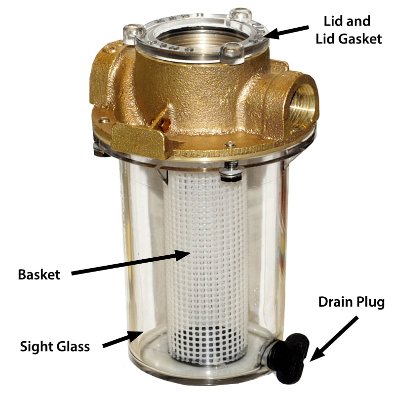
A raw-water strainer is the first line of defense; it’s only meant to keep out relatively large debris. Photo courtesy of Groco.
No matter how sophisticated your raw-water strainer is, understand that it was only designed to keep weed and other relatively large debris from entering your cooling system and clogging the raw-water pump. Things like micro-organisms, calcium, and lime are still getting by the strainer and are indeed going to leave deposits inside the raw/seawater side of your cooling system. Left unattended, this stuff will eventually form a coating inside the comparatively small passages inside your heat exchanger. Think of it as cholesterol plaque in your cooling system.
That buildup will cause a couple of bad things to happen. One is physical blockage of cooling water flow, which will obviously have an extreme effect before too long. The other is not so obvious; the buildup interferes with the heat transfer system itself, which utilizes both convection and conduction to get the job done. We’re attempting to move the heat from one liquid through a metal interface and into another liquid. Convection gets the heat from your engine’s coolant into contact with the tubes inside your heat exchanger, where it’s conducted through the metal walls of these this mini-pipes. Convection then carries the heat away from the pipes, into the seawater, and back overboard. Any buildup of coating on these tubes will block this heat transfer and reduce the overall efficiency of your heat exchanger, in some cases quite significantly. There have been plenty of cases where this one simple problem has caused engine overheating at high speeds.
So, what to do? Flush the raw-water side of your cooling system each year as a part of your winter layup procedure. A couple of products I’ve used are Seaflush and Forté cooling system flush.
Before you flush, be sure to remove the sacrificial anode(s) screwed into your heat exchanger, and replace the anodes with new ones after the flushing. This is especially important in a saltwater environment. For more of a step-by-step approach to this, read Winterizing Your Diesel Engine: Cooling System.
Besides keeping the “plaque” buildup out of the raw-water side of your cooling system, you should of course test your engine coolant to make sure it’s at an adequate protection level temperature-wise. Inexpensive antifreeze hydrometers to verify this are available at just about any automotive parts store.
If you’re checking your antifreeze and find that your system needs topping up, make sure you add exactly what’s already in your system. There are many variations available in the market today and they don’t all play well together chemically. Again, make sure you do not deviate from specific engine manufacturer recommendations for coolant.
Also, it pays to test the pressure cap on your cooling system every three or four years. They do eventually wear out. Most automotive shops have an appropriate pressure tester they can check this with, and it only takes a minute to perform the test. Or you can just replace the cap as part of your preventive maintenance The pressure rating is typically embossed on the cap.
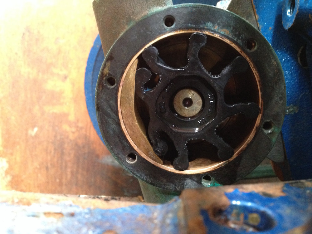
The raw-water pump impeller is a key component in the cooling system. Feed it clean water via your strainer, and change it as necessary. Doug Logan photo.
And don’t forget your raw-water pump impeller; this should be replaced every season or two, depending on how much you use your boat.
Following the guidelines here and your engine will be one cool operator come summertime!
Following the guidelines here and your engine will be one cool operator come summertime!
04/10/2021
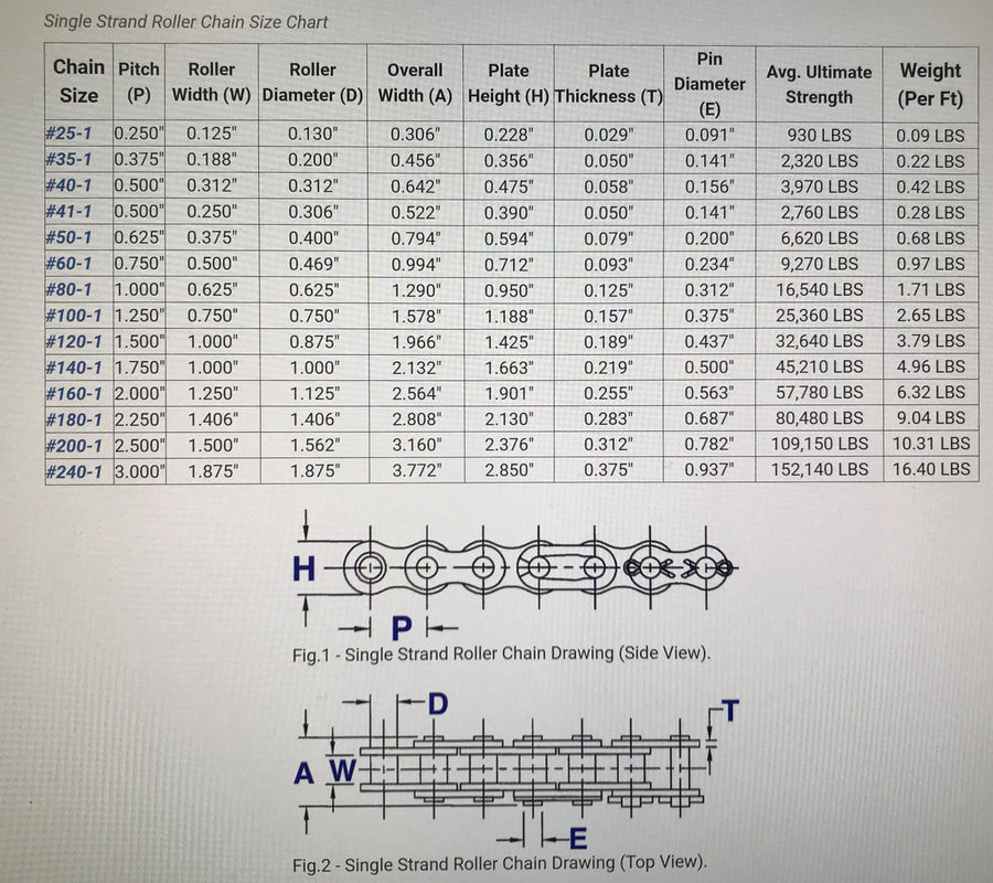
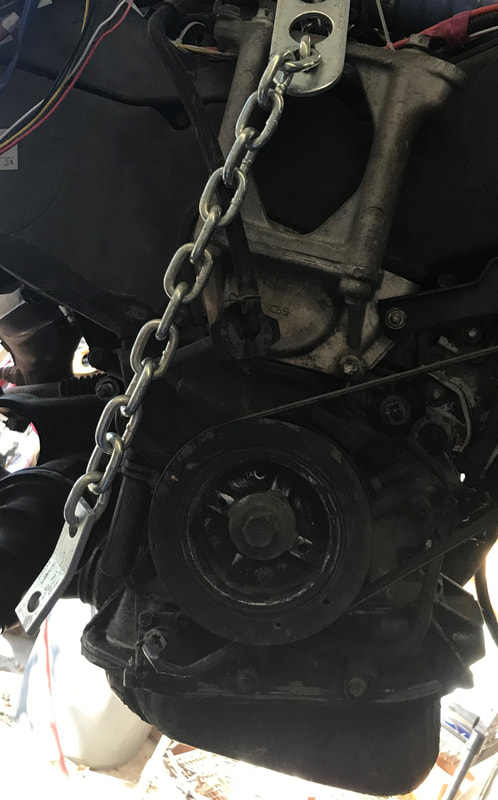
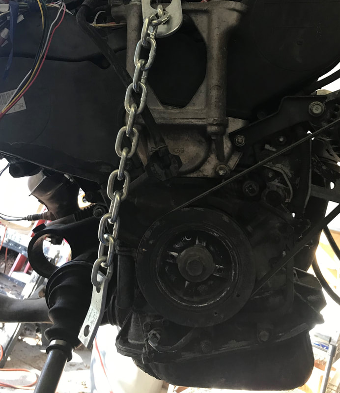
Got the drive shaft installed, now waiting for retaining snap ring and a 55 mm bore pillow bearing to come in to support the end of the shaft. Next trying to figure out what size of chain I really need. After finding a chain chart, I find the #40-1 chain I have been using is perfect. Avg Ultimate Strength of 3,970 lbs should do very nicely.
Got the drive shaft installed, now waiting for retaining snap ring and a 55 mm bore pillow bearing to come in to support the end of the shaft. Next trying to figure out what size of chain I really need. After finding a chain chart, I find the #40-1 chain I have been using is perfect. Avg Ultimate Strength of 3,970 lbs should do very nicely.
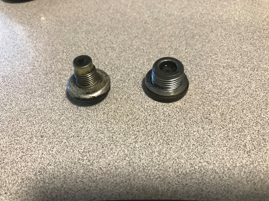
Hate to wait for parts to come in and not do anything else, so now working on extending the drains for the oil and transmission fluid. Oil nut is 12 mm and the transmission nut is 18 mm.
04/09/2021
Got the framing for the engine done! The engine is supported by three brackets and one shock asorber to reduce the engine from shaking and tilting when under strain. Next step is to weld the framing for the drive shaft. Spent some time organizing this blog and realized been at this reconstruction since 2017. Building is fast and easy, I can probably build a hull in about a month, but the experimentation is what eats all my time. Now the point of which portion of the build pushes me the most. I can place the engine in soon, but the decision will be to complete the motor, pumps drive systems and all with the transom still not in place, which allows easy access. But this requires the boat ti still remain in the sling. Or finish the hull, fiber and resin, paint and finally weld trailer and place boat back on safe supports of said trailer, but lose ease of access. I believe once motor is installed, which ever portion of the project gives me that excited energy is the way to go. I look at this as there is no wrong answer, just a different path towards the same goal.
Got the framing for the engine done! The engine is supported by three brackets and one shock asorber to reduce the engine from shaking and tilting when under strain. Next step is to weld the framing for the drive shaft. Spent some time organizing this blog and realized been at this reconstruction since 2017. Building is fast and easy, I can probably build a hull in about a month, but the experimentation is what eats all my time. Now the point of which portion of the build pushes me the most. I can place the engine in soon, but the decision will be to complete the motor, pumps drive systems and all with the transom still not in place, which allows easy access. But this requires the boat ti still remain in the sling. Or finish the hull, fiber and resin, paint and finally weld trailer and place boat back on safe supports of said trailer, but lose ease of access. I believe once motor is installed, which ever portion of the project gives me that excited energy is the way to go. I look at this as there is no wrong answer, just a different path towards the same goal.
Right side support and rear support
|
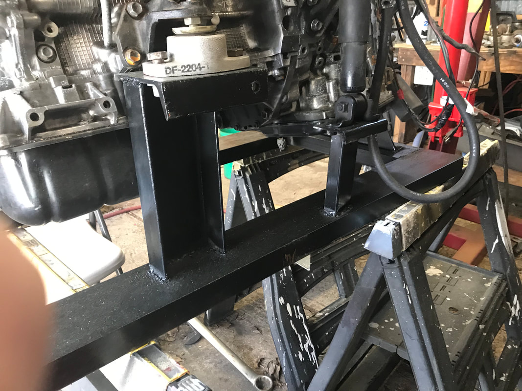
Left side support and shock absorber bracket
|
04/08/2021
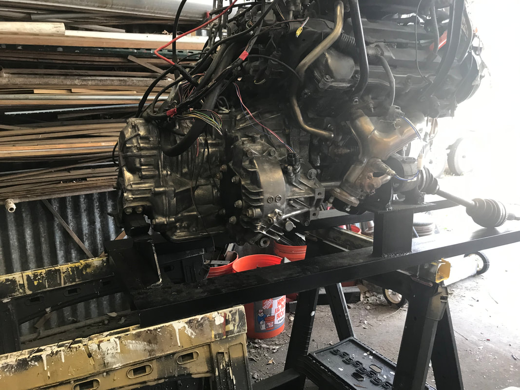
Major push forward. Was able to weld engine support frame together using original rubber supports (the rubber helps eliminate engine movements and shaking from transferring to the hull of the boat.) Had trouble with the right side support, trying to get it to screw to a flat plat, when I realized there was a 3/4" level difference between ends. After welding on a spacer, was able to just weld that bracket to the plate. There is 14" spacing between the left and right bottom frames. Now just need to weld a brace for the left shock absorber and engine mounting it done. Then I need to figure out how to mount the drive shaft to the frame. Left a large gap between frame and engine for several reasons. First I wanted to make sure my hand and arm would be able to work under engine, since otherwise would have to lift engine out of boat to be able to get at oil pan. Second, I also want changing out oil to be easy, so plan to route a tub from the bottom of the oil pan to a cut-off valve and then to the bottom of the hull. This way all I need to do is place a bucket to catch the old oil under the boat and then open a valve. The third reason is, I still need to run the exhaust pipe, and the engine is designed for them to be routed under the engine. I plan to route them into a water cooled heat exchanger, to limit the amount of heat that will be placed in the engine compartment. Then have to rig an external water pump to bring water from under the boat to be used in heat exchangers to replace the original radiator to cool the engine, and a heat exchanger for the transmission fluid. So many steps to go.
Major push forward. Was able to weld engine support frame together using original rubber supports (the rubber helps eliminate engine movements and shaking from transferring to the hull of the boat.) Had trouble with the right side support, trying to get it to screw to a flat plat, when I realized there was a 3/4" level difference between ends. After welding on a spacer, was able to just weld that bracket to the plate. There is 14" spacing between the left and right bottom frames. Now just need to weld a brace for the left shock absorber and engine mounting it done. Then I need to figure out how to mount the drive shaft to the frame. Left a large gap between frame and engine for several reasons. First I wanted to make sure my hand and arm would be able to work under engine, since otherwise would have to lift engine out of boat to be able to get at oil pan. Second, I also want changing out oil to be easy, so plan to route a tub from the bottom of the oil pan to a cut-off valve and then to the bottom of the hull. This way all I need to do is place a bucket to catch the old oil under the boat and then open a valve. The third reason is, I still need to run the exhaust pipe, and the engine is designed for them to be routed under the engine. I plan to route them into a water cooled heat exchanger, to limit the amount of heat that will be placed in the engine compartment. Then have to rig an external water pump to bring water from under the boat to be used in heat exchangers to replace the original radiator to cool the engine, and a heat exchanger for the transmission fluid. So many steps to go.
|
|
|
|
03/25/21
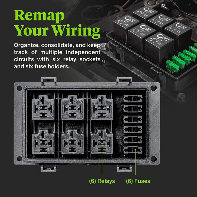
Been slowly editing the wiring diagram from the Haynes book of the car I took the motor from. First took out all missing components and then started to arrange so I could make my own circuit, instead of using the car fuse and relay boxes taken from off the vehicle. Bought a 12V Auto Waterproof Fuse Relay Box Block [6 Bosch Style Relay Holder] [6 ATC/ATO Fuse Holder] Universal Relay Block Box for 12V Automotive Vehicles Cars Marine Boat Light Equipment and was able to wire my circuit into just one box. Due to size and gauge of wires, bought the 100 and 40 amp fuses separate.
Been slowly editing the wiring diagram from the Haynes book of the car I took the motor from. First took out all missing components and then started to arrange so I could make my own circuit, instead of using the car fuse and relay boxes taken from off the vehicle. Bought a 12V Auto Waterproof Fuse Relay Box Block [6 Bosch Style Relay Holder] [6 ATC/ATO Fuse Holder] Universal Relay Block Box for 12V Automotive Vehicles Cars Marine Boat Light Equipment and was able to wire my circuit into just one box. Due to size and gauge of wires, bought the 100 and 40 amp fuses separate.
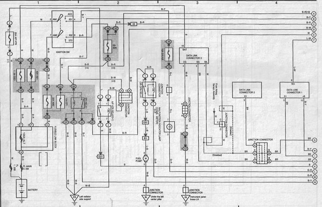
Scanned page from Haynes book
|
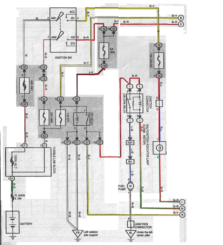
Edited diagram
|
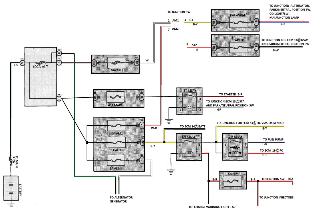
More simplified and ready for wiring a circuit.
|

|
02/18/21
Snowy day. Had cleaned the engine and what a difference it makes.
Snowy day. Had cleaned the engine and what a difference it makes.
|
|
02/07/2021
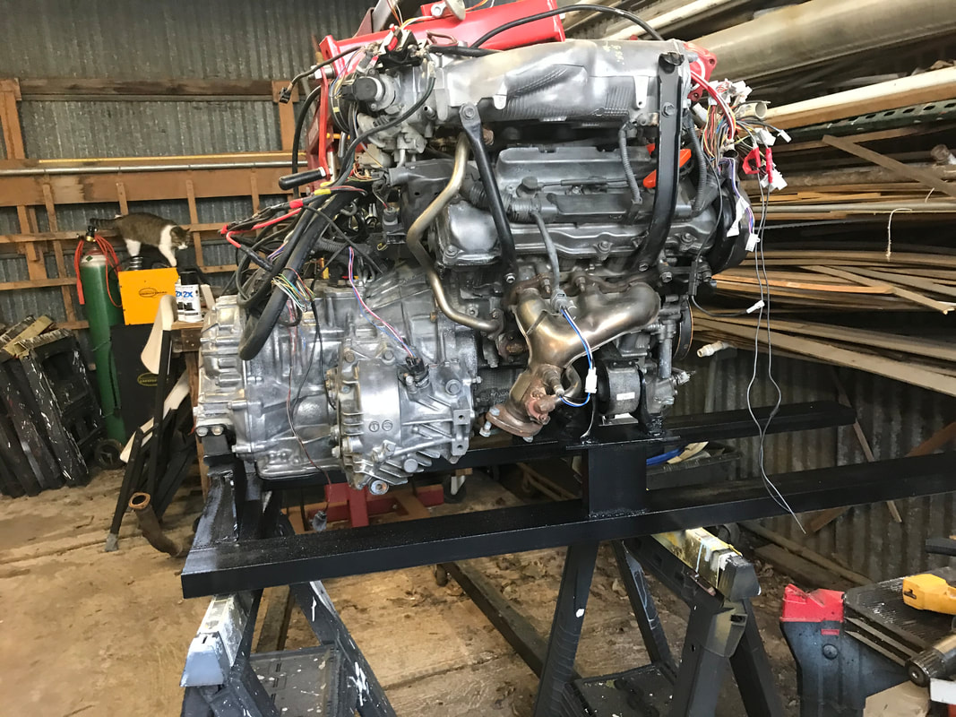
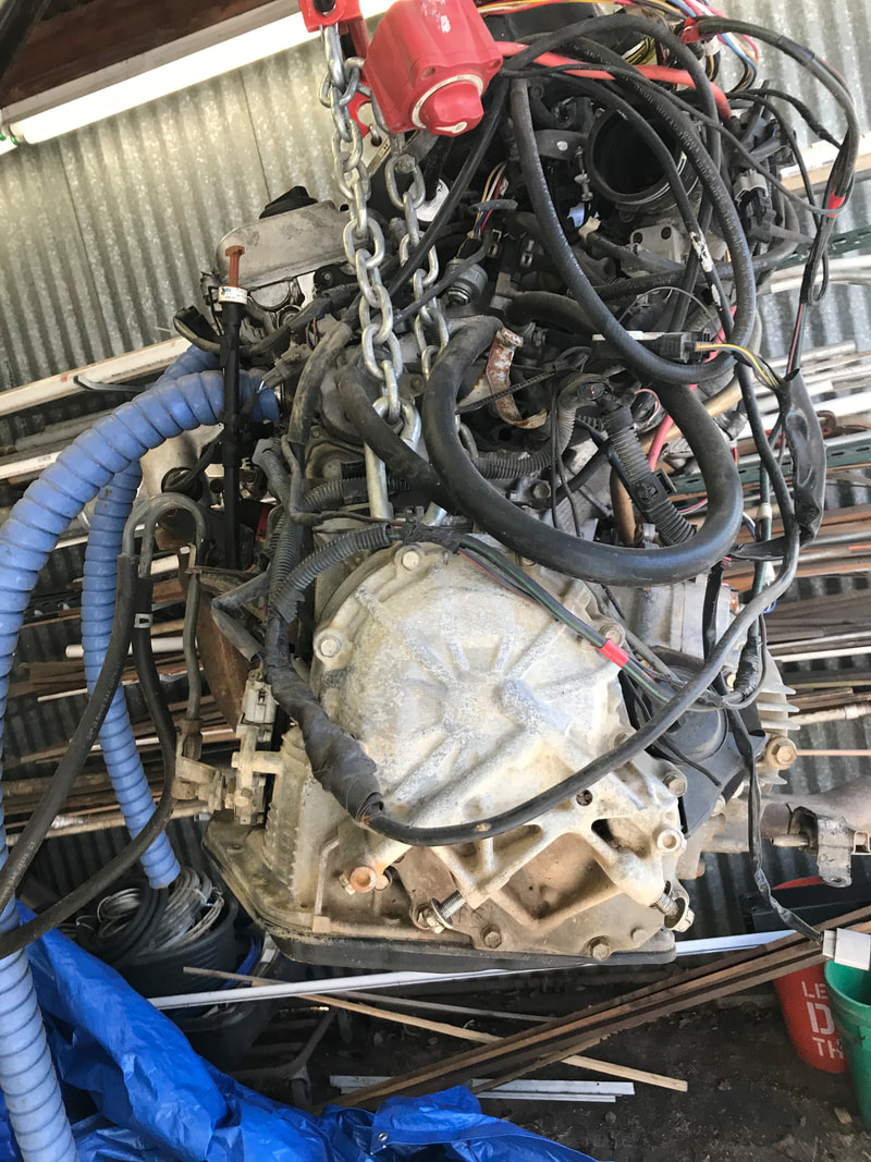
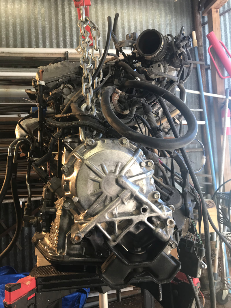
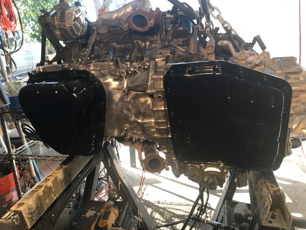
Good Morning! Been working to bring the engine back to a clean state. Still have a lot to do. Figured might as well clean as much as I can before putting into the boat. I did not know it would shine as much as it does. I turned and lowered the engine so I could clean while sitting and begin from the bottom Painted the oil and transmission pans, before I turn the engine at to better reach other sides.
Good Morning! Been working to bring the engine back to a clean state. Still have a lot to do. Figured might as well clean as much as I can before putting into the boat. I did not know it would shine as much as it does. I turned and lowered the engine so I could clean while sitting and begin from the bottom Painted the oil and transmission pans, before I turn the engine at to better reach other sides.
02/02/2021
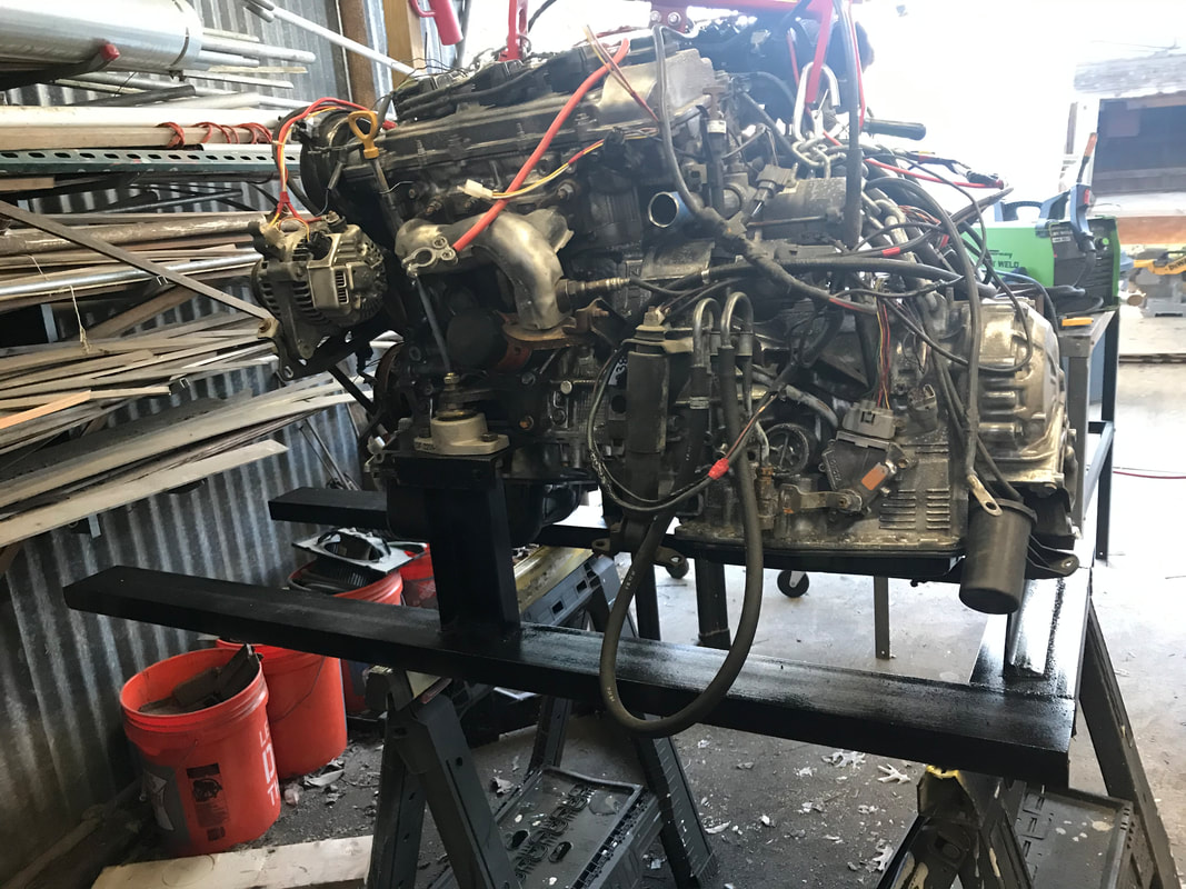
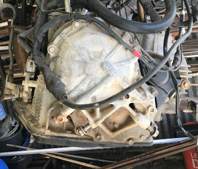
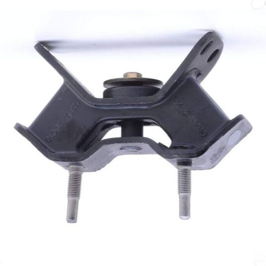
All righty then! Started work on making cradle for the engine. Was planning to use original mounting brackets, but after seeing the difficulty in trying use them and make cradle to conform, and the area covered would have greatly over crowded the aft of the boat. Therefore it looks like it will be simplest to remove them and make my own. I began removing the mounting brackets, when I saw there were several brackets not being used, so I removed them as well. Then I noticed how dirty the motor was, so began wire brushing it clean. Since the transmission mount screws are tilted at such an odd angle, I decided to buy a new mount, but will make my own for the rest. The old one was split all the way through the rubber. It is difficult determining the correct tilt orientation of the engine. Viewing from the front, do I go by the bottom of the oil pan, the bottom of the engine, or the front bracket?
All righty then! Started work on making cradle for the engine. Was planning to use original mounting brackets, but after seeing the difficulty in trying use them and make cradle to conform, and the area covered would have greatly over crowded the aft of the boat. Therefore it looks like it will be simplest to remove them and make my own. I began removing the mounting brackets, when I saw there were several brackets not being used, so I removed them as well. Then I noticed how dirty the motor was, so began wire brushing it clean. Since the transmission mount screws are tilted at such an odd angle, I decided to buy a new mount, but will make my own for the rest. The old one was split all the way through the rubber. It is difficult determining the correct tilt orientation of the engine. Viewing from the front, do I go by the bottom of the oil pan, the bottom of the engine, or the front bracket?
|
|
|
|
SLIDE SHOW OF BOAT BUILD
Just got back from a family vacation only to realise I have another trip in one week. Will be putting off boat build till I get back. Vacation allowed me to reread Glen's plywood boat building book, and decided to make frames from 1"x4"s instead of 2"x4"s. Also need to have 6" overlap on gussets. Will just need a little tweeking of the drawings.

Here is the Last boat!
Found a great sight for metal parts.Bought shaft, mouting bearings, flanges for wheel and gears for 40 chain. This will make the paddlewheel assembly easier, and will not have to weld spindles to plumbing pipe for shaft.
MCmaster-Carr
MCmaster-Carr